



Contents: Removal ⤓ Engine since 2000 ⤓ All engines ⤓ Engine since 2000 ⤓ All engines ⤓ Installation ⤓ Engine since 2000 ⤓ All engines ⤓ Engine since 2000 ⤓ All engines ⤓
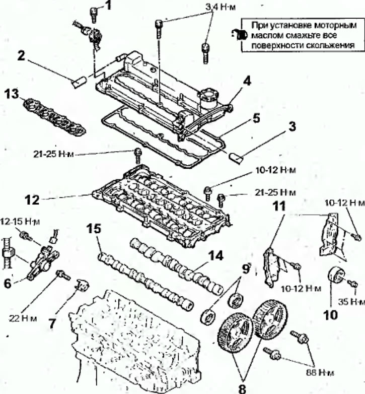
Fig. 2.16. Camshafts and camshaft seals of the engine since 1999: 1 - Fuel injector wiring harness support bracket; 2 - crankcase ventilation hose; 3-hose PCV; 4 - cylinder head cover; 5- cylinder head roof gasket; 6 - base of the camshaft position sensor; 7 - cylindrical rotor of the camshaft position sensor; 8 - camshaft pulley; 9 - camshaft oil seal; 10 - Idle pulley; 11- rear timing belt cover; 12—camshaft cover; 13 - camshaft cover gasket; 14 - exhaust camshaft;15 - intake camshaft
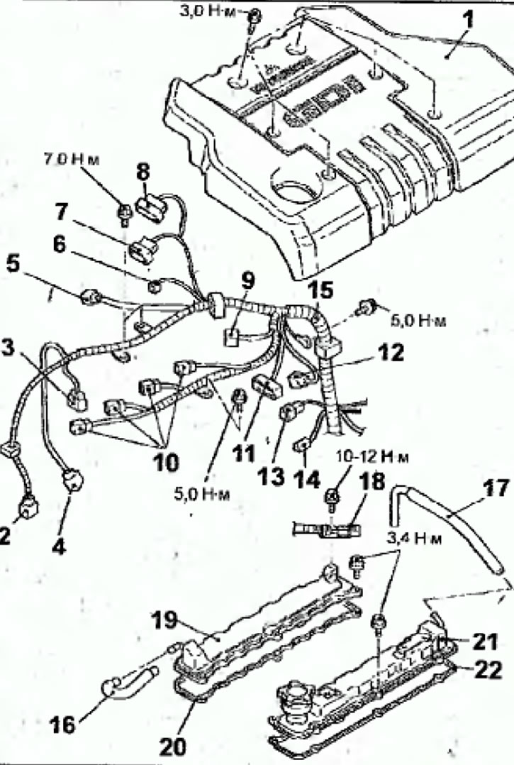
Fig. 2.17. Camshafts and camshaft seals of the engine since 2000: 1-engine cover; 2 - crankshaft angle sensor connector: 3 - fuel pressure sensor connector; 4 - Front oxygen concentration sensor connector; 5 - control and EGR wiring harness connector; 6- connector of the electromagnetic valve for cleaning the adsorber; 7 - throttle position sensor connector; 8 - Throttle control servo connector; 9 - connector of control and injector wiring harness; 10 - ignition coil connectors; 11 - ignition misfire detection sensor connector; 12 - camshaft position sensor connector;13 - coolant temperature sensor connector; 14 - coolant temperature gauge sensor connector; 15 - control wiring harness; 16—PCV hose; 17 - crankcase ventilation hose; 18 - connector bracket (injector wiring harness); 19 - cylinder head cover (intake side); 20 - cylinder head cover gasket; 21 - cylinder head cover (from the exhaust side); 22 - Cylinder head cover gasket
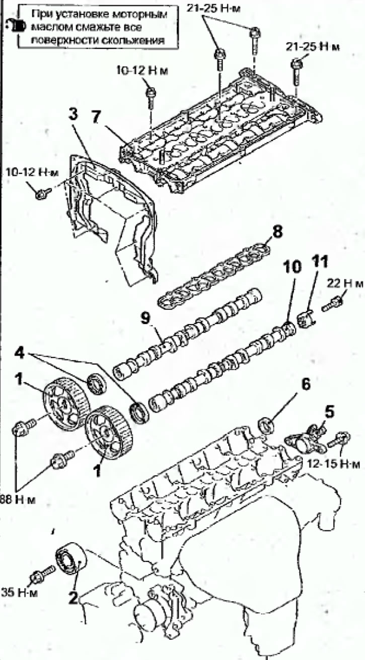
Fig. 2.18. Camshafts and camshaft seals of the engine since 2000: 1 - camshaft pulley; 2 - idle pulley; 3 - Upper rear toothed belt cover; 4 - camshaft oil seal; 5 - base of the camshaft position sensor; 6 - round plug; 7 - camshaft cover; 8 - camshaft cover gasket; 9 - intake camshaft; 10 - exhaust camshaft; 11 - cylindrical rotor of the camshaft position sensor
Removal
- Disconnect the cable from the negative battery terminal.
- Loosen the clamps and remove the air intake pipe.
Engine since 2000
- Remove the air filter.
- Drain the coolant from the cooling system.
- Remove the screws and remove the engine cover.
All engines
- Remove the timing belt of the gas distribution mechanism drive.
- Remove the intake manifold.
- Remove the camshaft high pressure pump housing (see the relevant chapter in the section "Direct fuel injection system (GDI)").
Engine since 2000
- Disconnect the connectors from the crankshaft angle sensor(2), Figure 2.17, fuel pressure sensor (3), front oxygen concentration sensor (4), control and EGR wiring harness (5), adsorber cleaning solenoid valve (6), throttle position sensor (7), throttle control servo (8), control wiring harness and injectors (9), ignition coils (10), misfire detection sensor (11), camshaft position sensor (12), coolant temperature sensor (13), coolant temperature indicator sensor (14) and control wiring harness (15).
- Disconnect the connectors, unscrew the bolts and remove the ignition coils.
- Remove the intake manifold.
- Remove the timing belt of the gas distribution mechanism drive.
- Remove the bolt and bracket from the injector wiring harness connector.
- Remove the bolts and cylinder head covers.
- Remove the cylinder head cover gaskets.
- Remove the bolts and high pressure fuel pump.
All engines
- Remove the bolt and fuel injector harness support bracket.
- Disconnect the crankcase ventilation hose from the pipe on the cylinder head cover.
- Disconnect the PCV hose from the fitting on the cylinder head cover.
- Remove the bolts and remove the cylinder head cover.
- Remove the cylinder head cover gasket.
- Disconnect the electrical connector, remove the bolts, and remove the camshaft position sensor base.
- Remove the bolt and camshaft position sensor cylindrical rotor.
- Using special tools MD998719 and MB990767, block the camshaft pulley from turning and unscrew the pulley mounting bolt (Fig. 2.19). Remove the pulleys from the camshafts.
- Using a knife or a flat-head screwdriver, make a groove near the working edge of the seal.
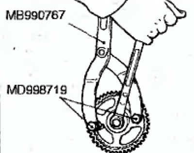
Fig.2.19. Using special tools to block the camshaft pulley from turning
Warning: Be careful not to damage the camshaft and cylinder head.
- Insert a flat-head screwdriver blade wrapped in cloth into the punched groove and, using the screwdriver as a lever, remove the seal
- Remove the bolt and the idler pulley of the timing belt.
- Remove the bolts and rear timing belt covers.
- Gradually, in several passes, unscrew the bolts and remove the camshaft cover from the cylinder head.
- Remove the camshaft cover gasket.
- Remove the camshafts from the cylinder head.
Installation
- Installation is carried out in the reverse order of removal, taking into account the following.
- Lubricate the camshaft journals and cams with engine oil.
- Install the camshafts into the cylinder head.
Warning. Do not confuse the camshafts of the intake and exhaust valves. The camshaft of the exhaust valves has a hole in the rear end for the bolt for fixing the cylindrical rotor of the camshaft position sensor (Fig.
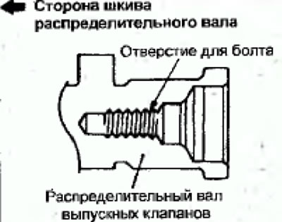
Fig. 2.20. Location of the hole on the rear end of the exhaust camshaft
- Position the camshaft dowel pins as shown in Figure 2.21.
- Apply a layer of sealant to the camshaft cover and cylinder head in the areas shown in Figure 2.22.
- Install the gasket and camshaft cover.
- Gradually, in several passes, in the sequence shown in Figure 2.23, screw in the camshaft cover mounting bolts and tighten them to the required torque.
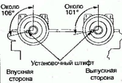
Fig. 2.21. Location of the dowel pins when installing the camshafts
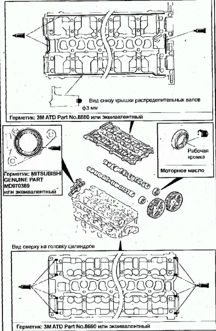
Fig. 2.22. Places for applying sealant and lubrication to the camshaft oil seal
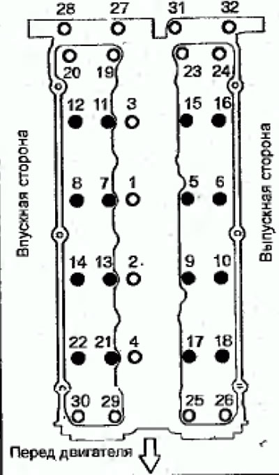
Fig. 2.23. Sequence of tightening the cylinder head cover bolts
Tightening torque:
- bolts marked with a black circle: 10-12 Nm
- bolts marked with a white circle: 21-25 Nm
- Lubricate the working edge of the camshaft oil seal with engine oil.
- Using a special tool, press in the camshaft seals (Fig. 2.24).
- Install the camshaft pulleys and secure with bolts. Using special tools MD998719 and MB990767, lock the camshaft pulley from turning and tighten the pulley mounting bolt to a torque of 88 N·m (see Fig. 2.19).
- Install and secure the camshaft position sensor cylindrical rotor with the bolt.
- Install and bolt the camshaft position sensor base. Connect the electrical connector to the camshaft position sensor.
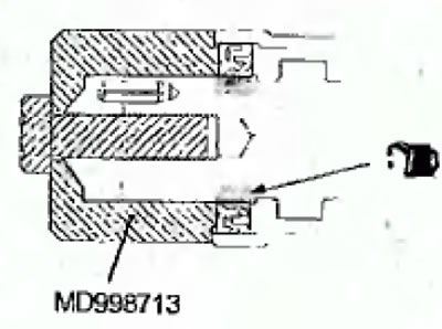
Fig.2.24 Using a special tool to press in the camshaft seal
Engine since 2000
- Using a special tool, press in the cool plug as shown in Figure 2.25.
The original article was published on [www.mitsubishiman.ru]
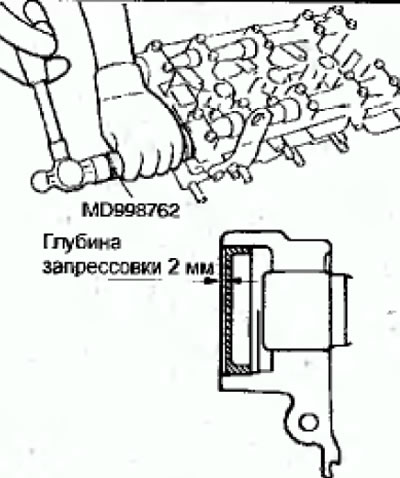
Fig. 2.25. Using a hammer and a special tool to press in a round plug
All engines
- Install the cylinder head cover gasket.
- Install and bolt the cylinder head cover
- Connect the PCV hose to the fitting on the cylinder head cover.
- Connect the crankcase ventilation hose to the fitting on the cylinder head cover
- Install the fuel injector harness support bracket.
- Install the camshaft high pressure pump housing.
- Install the intake manifold.
- Install the timing belt to drive the gas distribution mechanism.
- Install the air intake pipe.
Engine since 2000
- Install the engine cover and tighten the mounting bolts by hand until the cover can be moved. Tighten the engine cover mounting bolts to 3.0 N·m in the sequence shown in Figure 2.26.
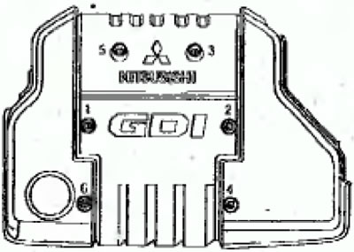
Fig. 2.26. Sequence of tightening the engine cover mounting bolts
All engines
- Connect the cable to the negative terminal of the battery.