



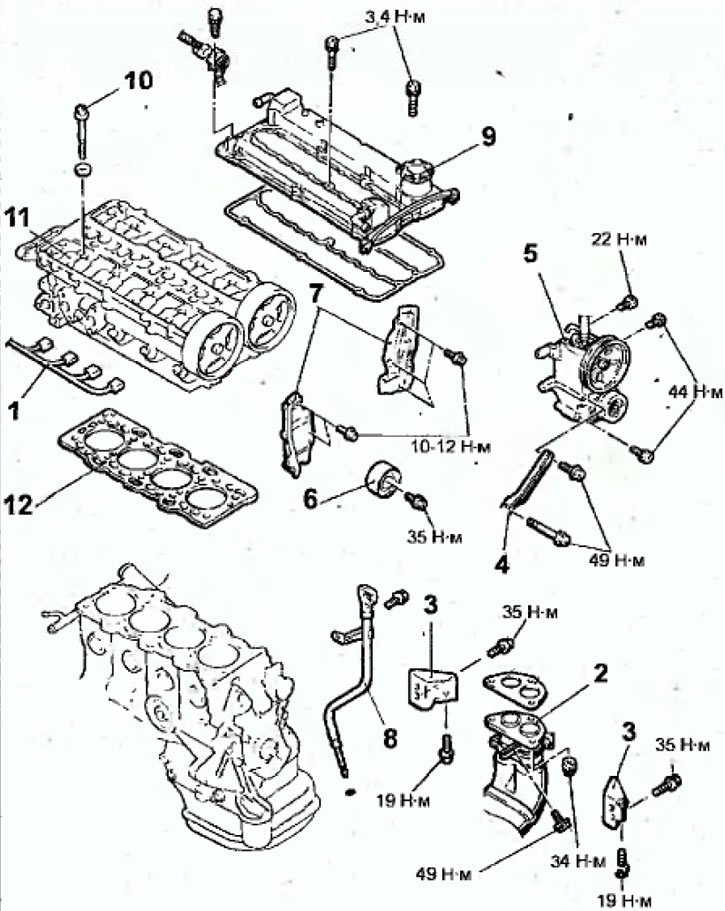
Fig. 2.35. Cylinder head of the engine produced since 1999: 1- Electrical connectors of the injector wire harness; 2 - exhaust inlet pipe; 3 - exhaust manifold bracket; 4 - Power steering pump support bracket;5 - Power steering pump and bracket; 6 - Idle pulley; 7 - rear toothed belt covers; 8-guide tube of engine oil level indicator; 9 - cylinder head cover; 10 - cylinder head mounting bolt, 74 Nm + loosen + 20 Nm + 90°+90°; 11 Cylinder head assembly; 12 - cylinder head gasket.
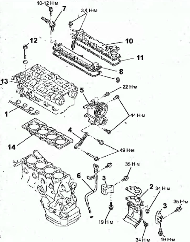
Fig. 2.37. Cylinder head of the engine produced since 2000: 1 - injector wiring harness connector; 2 - exhaust inlet pipe; 3 - exhaust manifold bracket; 4 - Power steering pump support bracket; 5 - Power steering pump and bracket; 6 - Engine oil level indicator guide tube; 7 - injector wiring harness bracket, 8 - cylinder head cover (from the exhaust side); 9 - cylinder head cover gasket; 10 - cylinder head cover (from the exhaust side); 11 - cylinder head cover gasket, 12 - cylinder head mounting bolt, 74 Nm + loosen + 20 Nm + 90° + 90°, 13 - cylinder head assembly, 14 - cylinder head gasket
The valve timing components are installed and operate in the cylinder head. To improve thermal conductivity and reduce weight, the cylinder head is made of a light alloy. It is exposed to high temperatures and gas pressure and therefore has a rigid lower support surface and is intensively cooled by liquid, and the wall thickness is made as uniform as possible to reduce internal stresses from thermal expansion. The valve seats are pressed into the heated cylinder head and after it cools down, a strong, reliable connection is obtained. Each combustion chamber has threaded holes for spark plugs. The threads in the holes can be damaged if the spark plug is tightened with too much tightening torque or is screwed in with a transfer and tightened with a high tightening torque.
The gasket between the engine block and head is designed to keep the combustion chambers and coolant passages separated from each other, and it must not allow engine oil to pass through and must withstand high temperature and pressure fluctuations.
Removal
- Disconnect the cable from the negative battery terminal.
- Reduce the pressure in the fuel system.
- Drain the coolant from the cooling system.
- Remove the plug and drain the engine oil from the engine.
- Remove the timing belt of the gas distribution mechanism drive.
- Remove the intake manifold.
- Remove the high pressure fuel pump and fuel pressure regulator, and use a towel or rag to collect any leaked fuel.
- Remove the LGR valve.
- Remove the thermostat and upper radiator hose.
- Disconnect the electrical connectors from the fuel injectors.
- Loosen the nuts securing the exhaust pipe flange to the exhaust manifold.
- Remove the bolt and disconnect the exhaust inlet pipe from the exhaust manifold.
- Remove the bolts and exhaust manifold bracket.
- Remove the bolts and remove the power steering pump along with the attached hose and bracket.
Note: Use a cord or soft wire to secure the removed power steering pump to the engine compartment so that it does not interfere with the removal of the cylinder head.
- Remove the bolt and idler pulley.
- Remove the bolts and rear timing belt covers.
- Remove the bolt and the engine oil level indicator guide tube together with the sealing ring.
- Remove the bolts and remove the cylinder head cover.
- Using a special tool, in 2 or 3 steps in the sequence shown in Figure 2.36, loosen and unscrew the cylinder head mounting bolts
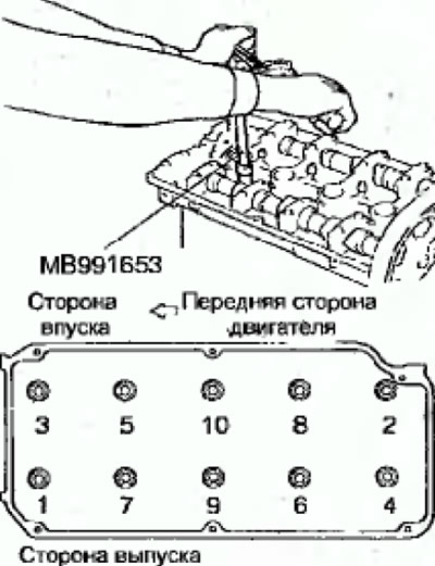
Fig. 2.36. Sequence of unscrewing the cylinder head mounting bolts
- Carefully remove the cylinder head.
- Remove the cylinder head gasket.
- Cover the engine cylinders with a clean, lint-free cloth.
Preparing for installation
- The mating surfaces of the cylinder head and block must be completely clean. Use a hard plastic or wooden scraper to clean them. Be careful when cleaning, as the aluminum alloy is very easy to damage. Check that carbon deposits do not get into the oil and water channels. This is especially important for the lubrication system, as carbon deposits can block the oil supply to the engine components. Clean the channels if necessary.
- Check the mating surfaces of the cylinder head and block for nicks, deep scratches and other damage. If the defects are small, remove them by mechanical treatment. However, if the defects are significant, the parts must be replaced.
- Check the cylinder head flatness with a metal ruler and feeler gauges in six directions. If necessary, regrind the cylinder head.
- Using a metal ruler and feeler gauge, measure the flatness of the mating surfaces of the manifolds in two directions.
- Clean the bolt holes in the cylinder block. Driving a bolt into an oil-filled hole can cause the block to burst due to hydraulic pressure.
Installation
Installation is carried out in the reverse order of removal, taking into account the following.
- Degrease the mating surfaces of the blocks and cylinder heads.
- When installing, check that all holes on the gasket and cylinder head match
- Install the gasket and cylinder head onto the cylinder block
- Check the condition of the cylinder head bolts and especially their threads. Measure the length of each bolt (excluding washer) from the underside of the bolt head to the end of the bolt. If the length of the bolts (A, Fig. 2.38) is less than 96.4 mm, they can be reused. If any bolt exceeds the specified length, shade all bolts in the set.
- Install washers on the cylinder head under the head mounting bolts, with the rounded side facing up, as shown in Figure 2.38.
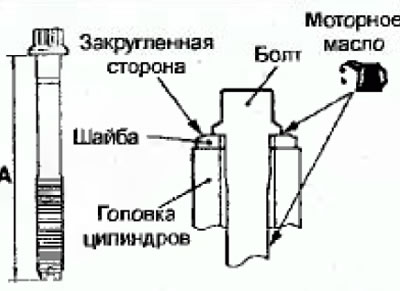
Fig. 2.38. Location of the cylinder head mounting bolt and washer: A = 96.4 mm
- Before installation, lubricate the top surface of the washer and the bolt threads with engine oil.
- Tighten the cylinder head mounting bolts in several stages in the sequence shown in Figure 2.39.
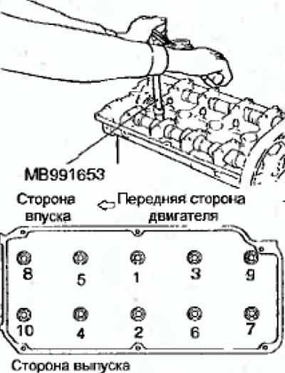
Fig. 2 39. Cylinder head bolt tightening sequence
Bolt tightening steps:
- step 1: Tighten to 74 Nm
- step 2: Loosen all bolts completely in the reverse order shown in Figure 2.39
- step 3: Tighten to 20 Nm
- step 4: Tighten the bolts by 90°. Mark the bolt heads and cylinder head with paint (Fig. 2.40)
- step 5: Tighten the bolts another 90°. The marks on the bolts and the cylinder head should be in line (Fig. 2.40)
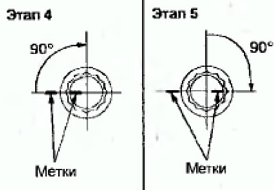
Fig. 2.40. Turning the cylinder head mounting bolts
Warnings
(1) Always tighten the bolt at an angle exactly equal to 90°, otherwise, the cylinder head mounting bolt may become loose (the reliability of the gas connection will not be ensured)
(2) If the bolt is turned to an angle greater than 90°, it is necessary to completely loosen it and repeat all bolt tightening operations
(The text of the article was obtained from the website: MitsubishiMan.ru)
- Install the cylinder head cover and secure with bolts, tightening them to the required torque.
- Install the engine oil level indicator guide tube together with a new sealing ring and secure with the bolt
- Install the rear timing belt covers.
- Install the idler pulley and secure it with the bolt, tightening it to the required torque.
- Install the power steering pump bracket.
- Install the exhaust manifold bracket and secure with bolts, tightening them to the required torque.
- Install the exhaust pipe flange onto the exhaust manifold and secure with nuts, tightening them to the required torque.
- Install the upper radiator hose and thermostat.
- Install the EGR valve.
- Install the fuel pressure regulator and high pressure fuel pump and secure with bolts, tightening them to the specified torque.
- Install the intake manifold.
- Install the timing belt to drive the gas distribution mechanism.
- Fill the engine with the required amount of recommended motor oil.
- Fill the cooling system with coolant
- Connect the cable to the negative terminal of the battery.
- Start the engine and check for leaks.