



Contents: Removal ⤓ Installation ⤓
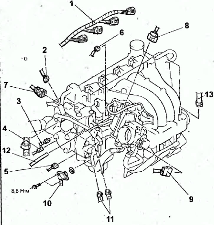
Fig. 2.60. Connection points for connectors and hoses to the engine since 1999: 1 - ignition coil connector; 2 - camshaft position sensor connector; 3 - coolant temperature sensor connector; 4 - coolant temperature gauge sensor connector; 5 - Engine sensor connector; 6 - connector of the electromagnetic valve for cleaning the adsorber; 7 - fuel pressure sensor connector; 8 - Throttle control servo connector; 9 - throttle position sensor connector; 10 - high pressure fuel hose connection; 11 - Fuel return hose connections; 12 - Vacuum hose connection; 13 - connection of the vacuum hose of the brake booster.
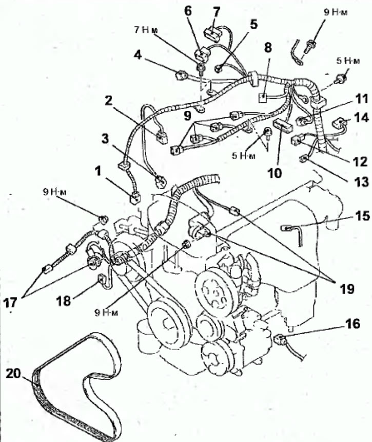
Fig. 2.61. Connection points for connectors and hoses to the engine since 2000: 1 - crankshaft angle sensor connector; 2 - fuel pressure sensor connector; 3 - Front oxygen concentration sensor connector; 4 - control and EGR wiring harness connector; 5 - connector of the electromagnetic valve for cleaning the adsorber; 6 - throttle position sensor connector; 7 - Throttle control servo connector; 8 - injector wiring harness connector; 9 - ignition coil connector; 10 - ignition misfire detection sensor connector; 11 - camshaft position sensor connector; 12 - coolant temperature sensor connector; 13- coolant temperature gauge sensor connector; 14 - knock sensor connector; 15 - Power steering hydraulic pressure sensor connector; 16 - air conditioning compressor connector; 17 - Generator connector; 18 - Engine oil pressure sensor connector; 19 - starter connector; 20 - Power steering pump and air conditioning compressor drive belt
Removal
- Disconnect the cable from the negative battery terminal.
- To remove, follow these steps in sequence.
- Relieve the fuel pressure in the fuel system. See chapter "Reducing pressure in the fuel system", given in the section "Direct Fuel Injection (GDI) System".
- Drain the coolant from the engine cooling system.
- Remove the hood.
- Remove the radiator.
- Remove the gearbox.
- Remove the screws and remove the cover from the engine.
Warning: In Figures 2.63 and 2.62, the elements marked with an (*) must be pre-tightened during installation and finally tightened after the vehicle has been lowered onto its wheels.
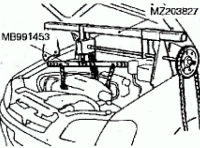
Fig. 2.62. Using a crossbeam to lift the engine from the engine compartment
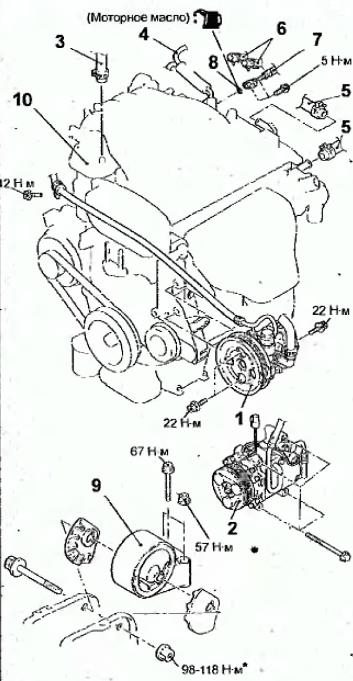
Fig. 2.63. Removable elements and engine mounting elements since 2000: 1 - Power steering pump; 2 - air conditioning compressor; 3 - connection of the vacuum hose of the brake booster; 4 - vacuum hose connection; 5 - connection of heater hoses; 6 - Fuel return hose connections; 7 - high pressure fuel hose connection; 8 - sealing ring; 9 - engine bracket; 10 - engine
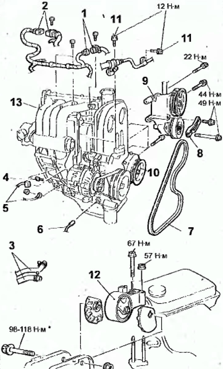
Fig. 2.64. Removable elements and engine mounting elements since 1999: 1 - crankshaft angle sensor connector; 2 - connector of injector wiring harness; 3 - connection of heater hoses; 4 - oxygen concentration sensor connector; 5 - generator connector; 6 - Engine oil pressure sensor connector; 7 - Power steering pump and air conditioning compressor drive belt; 8 - Power steering pump support bracket; 9 - Power steering pump and bracket; 10 - air conditioning compressor; 11 - Power steering hydraulic cylinder hose mounting bolt; 13 - Engine bracket; 14 - engine
- Disconnect the connectors from the ignition coil, camshaft position sensor, coolant temperature sensor, coolant temperature gauge sensor, knock sensor, EVAP purge solenoid valve, fuel pressure sensor, throttle control servo and throttle position sensor.
- On engines produced since 2000, disconnect the connectors from the starter power steering hydraulic pressure sensor, fuel pressure sensor and misfire sensor.
- On engines produced since 2000, disconnect the heater hoses.
- Remove the bolts, disconnect the high pressure fuel hose and remove the O-ring seal.
- Loosen the clamps and remove the fuel return slag.
- Disconnect the vacuum hoses.
- Disconnect the brake booster vacuum hose.
- Disconnect the connectors from the crankshaft angle sensor, injector wiring harness, oxygen sensor, generator and engine oil pressure sensor.
- Loosen the clamps and disconnect the heater hoses.
- Loosen and remove the power steering pump and air conditioning compressor drive belt.
- Remove the bolts and remove the power steering pump along with the attached hose and bracket.
Note: Use a cord or soft wire to secure the removed power steering pump to the engine compartment so that it does not interfere with engine removal.
- Disconnect the connector, unscrew the bolts and remove the air conditioning compressor together with the connected hoses from the bracket.
Note: Use a cord or soft wire to secure the removed compressor in the engine compartment so that it does not interfere with engine removal.
- Remove the bolt and disconnect the ground wire from the engine.
- Place a hydraulic jack under the engine.
- Remove the special tool used to remove the gearbox from the engine.
- Secure the engine to the crossbar and hang it on a hoist or similar device (Fig. 2.62).
- Place a block of wood between the jack base and the engine oil pan and lift the engine slightly to relieve the jack from the weight of the engine, then remove the engine mount bracket.
- Make sure all wires (electrical connectors), hoses, etc. are disconnected from the engine, and then slowly lift the engine up out of the engine compartment.
Installation
- Installation is carried out in the reverse order of removal, taking into account the following.
- When installing the motor, make sure that no wires, hoses or wire connectors are pinched.
- Place a hydraulic trolley jack under the engine (inserting a wooden block between the jack support foot and the engine oil pan) and install the engine support bracket, adjusting the engine position using the jack.
- Support the engine with a jack and disconnect the hoist.
- When installing the high pressure fuel hose, lubricate the O-ring with a small amount of engine oil (Fig. 2.65)
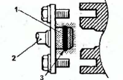
Fig. 2.65. Installing the high pressure fuel hose: 1 - engine oil lubrication point, 2 - fuel hose; 3 - O-ring gasket
Warning: Do not allow oil to enter the fuel line
- While slightly turning the flange of the fuel hose to the right and left, carefully insert it into the fuel line so as not to damage the O-ring seal. After installation, check that the hose rotates smoothly in the fuel line.
- If the hose flange sticks when turning, the O-ring may be damaged. Disconnect the flange (with hose) from the fuel line and check the O-ring for damage, then reinsert it and check for smooth turning.
- Install the high pressure fuel hose mounting bolts and tighten them to 5 Nm.
- On engines produced since 2000, install the fuel return hoses so that the marks on the hoses are in the positions shown in Figure 2.66.
(The material was borrowed from the website: «MitsubishiMan.ru»)
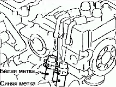
Fig. 2.66. Installation position of fuel return hoses