



The cross-section of the auxiliary cable must be at least 16 mm² (diameter 5 mm) for carburetor engines with a working volume of up to 2.5 l. For diesel engines and carburetor engines over 2.5 l, the cross-section must be at least 25 mm². The choice of cross-section also depends to a large extent on the state of charge of the battery. It is recommended to purchase an auxiliary cable with insulated clamps and a cross-section of 25 mm², as it is also suitable for engines with a smaller working volume.
Caution: If the vehicle with the discharged battery is equipped with the ABS system, Disable the anti-lock brake system, see item 18.16.
- Both batteries must have a nominal voltage of 12V.
- A discharged battery freezes already at -10°C. Before connecting the cable, be sure to let the frozen battery thaw.
- The discharged battery must be normally connected to the vehicle's electrical system.
- Check the electrolyte level in the discharged battery, add distilled water if necessary.
- If the battery banks have caps, loosen or unscrew them and cover both batteries with rags.
- Place both cars so that there is no metal contact between them. Otherwise, the current will flow only after connecting the positive terminals.
- On both vehicles, set the handbrake. Put the gearbox in neutral, set the automatic transmission to position "P".
- Turn off all energy consumers.
- Turn on the engine of the current-carrying vehicle to idle speed.
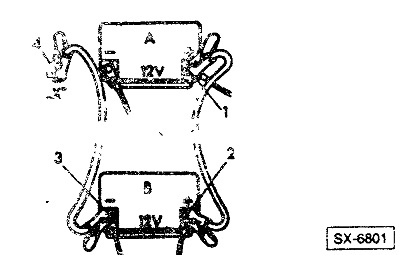
- Connect the auxiliary cable in the following sequence:
1. Connect the red wire to the positive pole of the discharged battery "A".
2. Connect the other end of the red wire to the positive pole of the current-conducting battery "B".
[The article was taken from the website: www.mitsubishiman.ru]
3. Connect the black wire to the negative terminal of the current-conducting battery.
4. Connect the other end of the black wire to a reliable ground connection point "X" of the vehicle to be started. This reduces voltage losses. The best option is to use a well-fastened part on the engine block or the block itself. If connected to the negative terminal of a discharged battery, under unfavorable circumstances the battery may explode due to the formation of a spark or explosive gas emission.
- Check the installation of the terminal clamps again. Make sure that the auxiliary cable cannot be damaged by rotating parts, such as the radiator fan impeller.
Caution: The auxiliary cable terminals must not be shorted when the cable is connected, and the positive terminals must not be in contact with ground (body or frame).
- Start the engine of the car with a discharged battery and leave it running. When starting, turn on the starter for no longer than 15 seconds, since the auxiliary cable and its clamps heat up from the high current? Therefore, take a break for cooling for at least ½ minute.
- The engine of a current-carrying vehicle must be idling when starting. This protects its generator from voltage surges during starting. When the speed drops, add gas to about 2000 rpm.
- Avoid approaching the battery with an open flame or lit cigarette during starting, as flammable gases may be released from the battery.
- Do not lean over the battery - risk of accident!
- After starting, disconnect the auxiliary cable in the reverse order. First disconnect the black cable on the current-receiving vehicle, then on the current-producing vehicle. Then disconnect the red cable first on the current-producing vehicle, then on the current-receiving vehicle.
Warning: Failure to follow the prescribed connection procedure may result in injury from battery acid discharge. There is also a risk of battery explosion and possible damage to the electrical systems of both vehicles.