



If there are leaks in the intake manifold, the vacuum of air entering the engine is reduced, which leads to malfunction of one or more cylinders.
Removal
- Disconnect the cable from the negative battery terminal.
- Drain the coolant from the engine cooling system.
- Remove the lower engine splash shield.
- Remove the air filter.
- Remove the ignition coils.
- Remove the throttle assembly.
- Disconnect the brake booster vacuum hose (Fig. 2.67).
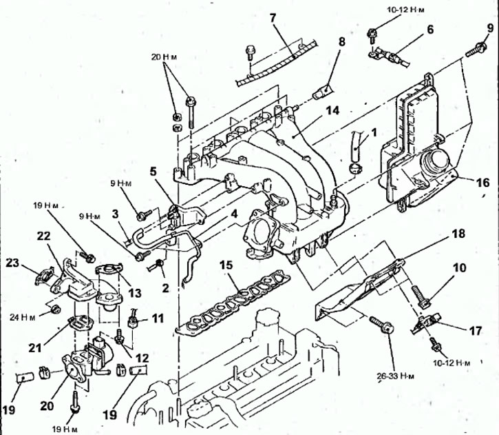
Fig. 2.67. Intake manifold: 1 - vacuum hose of the brake booster; 2 - connector of the electromagnetic valve for cleaning the adsorber; 3 - vacuum hose; 4 - vacuum hose and vacuum tube; 5 - electromagnetic valve for cleaning the adsorber; 6 - Crankshaft angle sensor connector bracket; 7 - Wiring harness fastening clamp; 8 - PCV crankcase ventilation hose; 9-bolts fastening the expansion air chamber to the intake manifold, 9 Nm; 10 - bolts for fastening the intake manifold support to the intake manifold, 26-33 N·m; 11-Exhaust gas recirculation (EGR)servo connector; 12- bolt, 12 Nm; 13 - EGR valve gasket, 14 - intake manifold; 15 - intake manifold gasket; 16 - expansion air chamber; 17 - clamp for fastening the oxygen concentration sensor wires; 18 - intake manifold support; 19 - engine cooling system hose; 20 - Exhaust Gas Recirculation (EGR) Valve; 21 - EGR valve gasket; 22- EGR valve base; 23 - EGR valve gasket
- Disconnect the connector from the purge solenoid valve.
- Disconnect the vacuum hose.
- Remove the vacuum hose and vacuum tube.
- Remove the purge solenoid valve.
- Remove the bolt and bracket for the crankshaft angle sensor connector.
- Remove the bolts securing the clamps from the wires.
- Disconnect the PCV hose.
- Remove the bolts securing the expansion chamber to the intake manifold.
- Remove the bolts securing the intake manifold support to the intake manifold.
- Remove the intake manifold mounting bolt to the EGR valve bracket and remove the gasket.
- Remove the bolts and nuts and remove the intake manifold and intake manifold gasket.
- Remove the expansion chamber.
- Loosen the bolt and remove the clamp securing the oxygen concentration sensor wire.
- Check the bolts and remove the intake manifold support.
- Disconnect the connector from the exhaust gas recirculation (EGR) servo.
- Disconnect the engine cooling system hose.
- Remove the bolts and exhaust gas recirculation (EGR) valve.
- Remove the EGR valve base mounting bolts and gasket.
Examination
- Check the intake manifold for cracks or other damage.
- Check the exhaust (vacuum) channel for blockages.
- Use a metal ruler and feeler gauges to measure the flatness of the intake manifold mating surface.
[The source of the article is available at: MITSUBISHIMAN]
Deviation from flatness of the intake manifold mating surface:
- nominal: no more than 0.15 mm
- maximum permissible: 0.20 mm
Installation
- Installation is carried out in the reverse order of removal, taking into account the following.
- Install the throttle assembly.
- Install the ignition coils.
- Install the air filter.
- Install the lower engine splash shield.
- Fill the engine cooling system with coolant.
- Connect the cable to the negative terminal of the battery.