
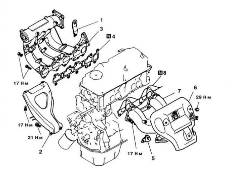
Details of installation of the inlet pipeline and an exhaust manifold on models 1.5 l (4G15 engine)
1 - Lifting eye of the power unit; 2 - Support column of the inlet pipeline; 3 - Inlet pipeline; 4 - Sealing gasket; 5 - Lifting eye of the power unit; 6 - Exhaust manifold cover; 7 - Exhaust manifold; 8 - Sealing gasket; N - Replace
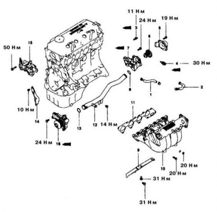
Details of installation of the inlet pipeline on models 1.8 l 1993 vol.
1 - Water path hose A; 2 - Water path hose B; 3 - Block of the coolant temperature meter; 4 - Coolant temperature sensor; 5 - Water inlet pipe; 6 - Thermostat; 7 - Thermostat casing; 8 - O-ring; 9 - Rack of the inlet pipeline; 10 - Inlet pipeline; 11 - Sealing gasket; 12 - Branch pipe of the water path; 13 - O-ring; 14 - Timing drive cover; 15 - Bracket of the left suspension support of the power unit; 16 - Water pump
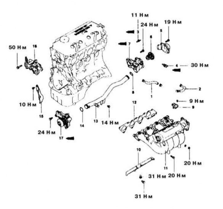
Details of installation of the inlet pipeline on models 1.8 l from 1994 to 2000.
1 - Water path hose A; 2 - Water path hose B; 3 - Block of the coolant temperature meter; 4 - Coolant temperature sensor; 5 - Water inlet pipe; 6 - Thermostat; 7 - Thermostat casing; 8 - O-ring; 9 - Differential pressure sensor in the pipeline (engines equipped with OBD II system); 10 - Rack of the inlet pipeline; 11 - Inlet pipeline; 12 - Sealing gasket; 13 - Branch pipe of the water path; 14 - O-ring; 15 - Timing drive cover; 16 - Bracket of the left suspension support of the power unit; 17 - Water pump
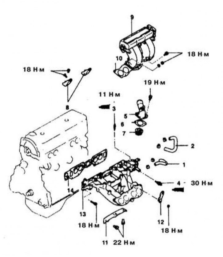
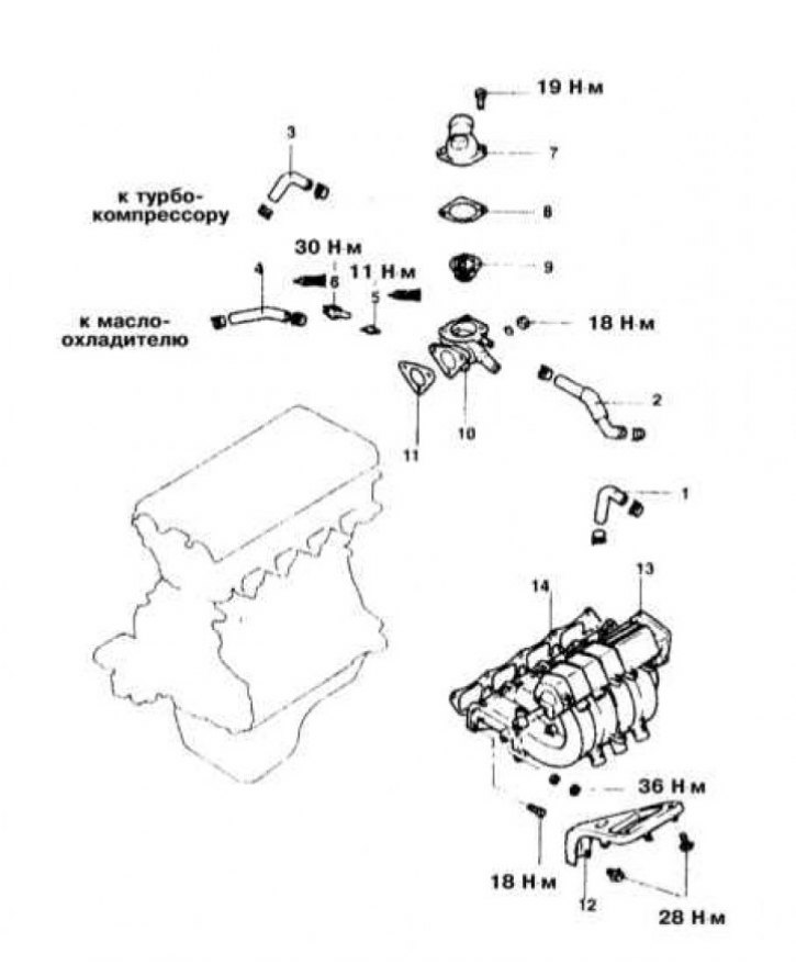
Intake Piping Installation Details on 2.0L SOHC Models
1 - Water path hose; 2 - Water path hose; 3 - Block of the coolant temperature meter; 4 - Coolant temperature sensor; 5 - Water outlet pipe; 6 - Sealing gasket; 7 - Thermostat; 8 - Rack of the discharge chamber of the inlet pipeline; 9 - Discharge chamber of the inlet pipeline; 10 - Sealing gasket; 11 - Rack of the inlet pipeline; 12 - Lifting eye of the power unit; 13 - Inlet pipeline; 14 - Sealing gasket
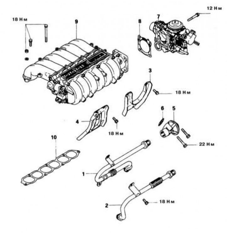
Intake piping installation details on 1.6L and 2.0L SOHC models
1 - Water path hose; 2 - Water path hose; 3 - Water path hose (turbo); 4 - Water path hose (turbo); 5 - Block of the coolant temperature meter; 6 - Coolant temperature sensor; 7 - Water outlet pipe; 8 - Sealing gasket; 9 - Thermostat; 10 - Thermostat casing; 11 - Sealing gasket; 12 - Rack of the inlet pipeline; 13 - Inlet pipeline; 14 - Sealing gasket
Installation details of the intake manifold pressure chamber on 3.0L DOHC models
1 - EGR pipe (California models through 1993 vol.); 2 - EGR pipe (California models since 1994 issue.); 3 - Rear rack of the inlet pipeline; 4 - A forward rack of the inlet pipeline; 5 - EGR valve (california models); 6 - Sealing gasket; 7 - Throttle body; 8 - Sealing gasket; 9 - Discharge chamber of the inlet pipeline; 10 - Sealing gasket of the discharge chamber
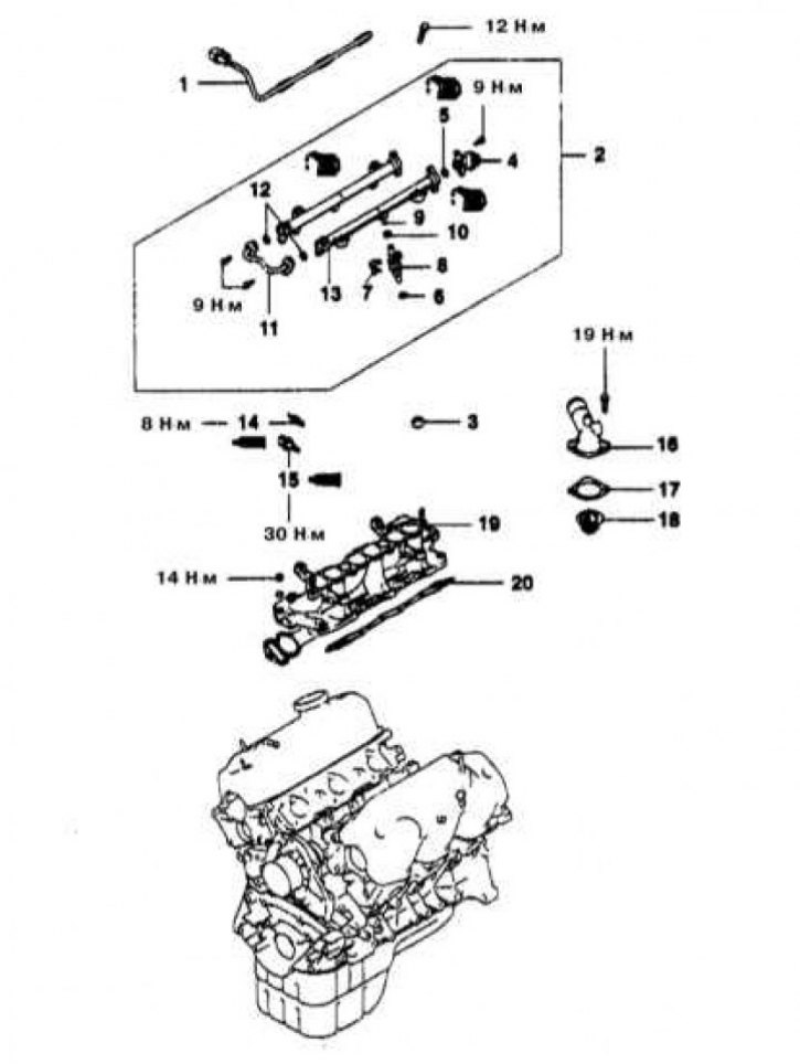
Intake Piping Installation Details on 3.0L DOHC Models
1 - Fitting for connecting the fuel supply line; 2 - O-ring; 3 - Fitting for connecting the fuel return line; 4 - Fittings for connecting vacuum hoses; 5 - Contact connectors for electrical wiring; 6 - Oxygen sensor (California models since 1994 issue.); 7 - Fuel line with injectors; 8 - Insulating sleeves; 9 - Top cover of the timing drive; 10 - Bolt of the water pump support bracket; 11 - Nut of fastening of the inlet pipeline; 12 - Nut of fastening of the inlet pipeline; 13 - Conical disc spring; 14 - Inlet pipeline; 15 - Gaskets
Installation details of the intake manifold pressure chamber on 3.0L SOHC models
1 - EGR pipe (California models through 1993 vol.); 2 - exhaust manifold support bracket; 3 - EGR pipe (1994 California Models / 1995 Federal Models); 4 - Ignition coil; 5 - BB wire; 6 - Rear rack of the inlet pipeline; 7 - A forward rack of the inlet pipeline; 8 - EGR pipe (California and federal models since 1995 vol.); 9 - EGR pipe seal (California and federal models since 1995 vol.); 10 - EGR temperature sensor (models equipped with OBD I system); 11 - Throttle body; 12 - Sealing gasket; 13 - Power transistor of the ignition system; 14 - Differential pressure sensor (models equipped with OBD II system); 15 - Discharge chamber of the inlet pipeline; 16 - Sealing gasket
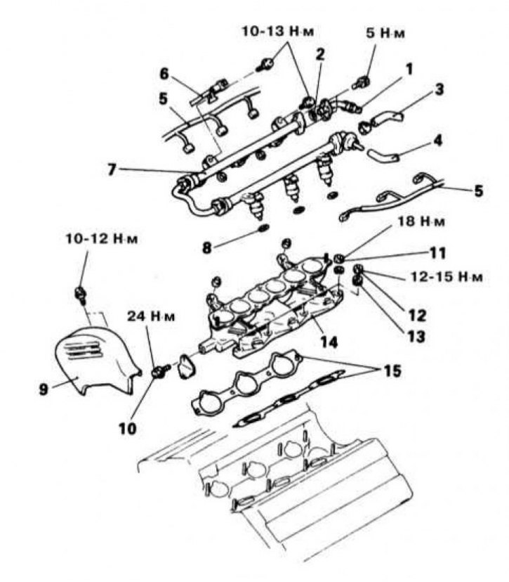
Intake Piping Installation Details on 3.0L SOHC Models
1 - Wiring of fuel injection injectors; 2 - Fuel line with injectors; 3 - Insulating sleeve; 4 - Fuel pressure regulator; 5 - O-ring; 6 - Insulating sleeve; 7 - Injector lock (models for 1993 issue.); 8 - Injectors; 9 - O-ring; 10 - Bushing; 11 - Fuel pipe; 12 - O-ring; 13 - Fuel line; 14 - Coolant temperature gauge; 15 - Coolant temperature sensor; 16 - Water outlet pipe; 17 - Sealing gasket; 18 - Thermostat; 19 - Inlet pipeline; 20 - Sealing gasket
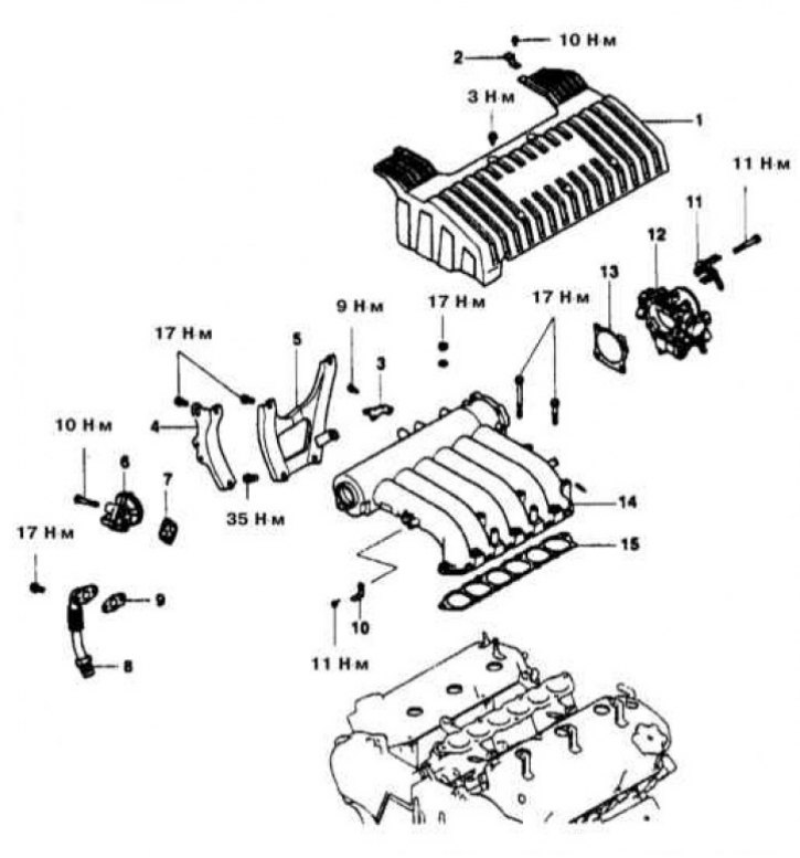
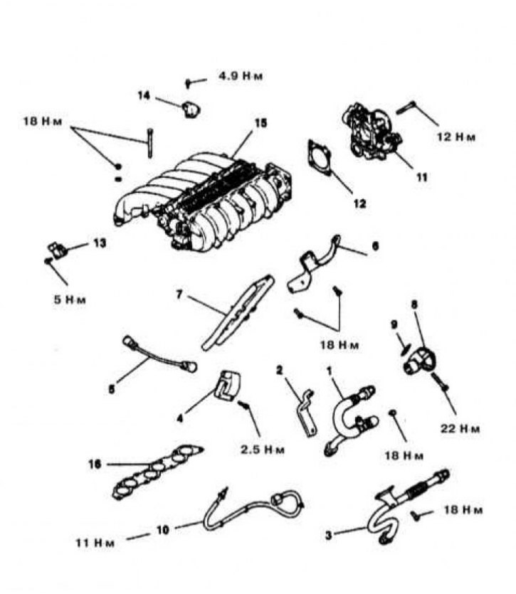
Intake manifold pressure chamber installation details on 3.5L models
1 - Engine cover; 2 - Retainer; 3 - Gas cable support bracket; 4 - A forward rack of the inlet pipeline; 5 - Rear pillar of the inlet pipeline; 6 - EGR valve; 7 - EGR valve gasket; 8 - EGR pipe; 9 - EGR tube gasket; 10 - Connector support bracket; 11 - Vacuum tube; 12 - Throttle body; 13 - Sealing gasket; 14 - Delivery chamber; 15 - Sealing gasket
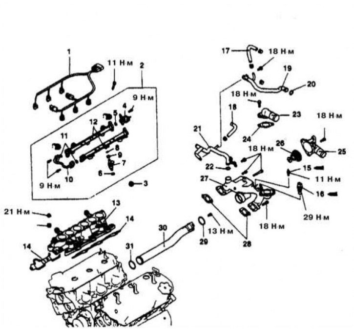
Details of installation of the inlet pipeline on models 3.5 l
1 - Engine wiring braid; 2 - Fuel line with injectors; 3 - Insulating sleeve; 4 - Fuel pressure regulator; 5 - O-ring; 6 - Insulating sleeve; 7 - Injector; 8 - O-ring; 9 - Bushing; 10 - Fuel pipe; 11 - O-ring; 12 - Fuel line; 13 - Inlet pipeline; 14 - Sealing gasket; 15 - Coolant temperature meter; 16 - Coolant temperature sensor; 17 - Water path hose; 18 - Water path hose; 19 - Inlet pipe of the heating path; 20 - O-ring; 21 - Inlet pipe of the heating path; 22 - O-ring; 23 - Water outlet pipe; 24 - Gasket of the exhaust pipe; 25 - Water inlet; 26 - Thermostat; 27 - Thermostat casing; 28 - Sealing gasket; 29 - O-ring; 30 - Tube of the water path; 31 - O-ring
Engines 1.5 l
Removing
1. The installation diagram of the inlet pipeline on 1.5 liter engines is shown in the illustration.
2. Follow all applicable fire safety precautions when working on power system components. Do not smoke! Do not approach the place of work with an open flame or carrying an unprotected lampshade! Do not service the system in rooms equipped with natural gas-fired heaters equipped with a pilot flame (such as water heaters and clothes dryers). Do not forget that gasoline is classified as a carcinogen, i.e., substances that contribute to the development of cancer! Try to avoid getting fuel on open areas of the body, use rubber protective gloves, in case of accidental unexpected contact with fuel, thoroughly wash your hands with warm water and soap. Clean up spilled fuel immediately and do not store fuel-soaked rags near open flames. Remember that the fuel injection system of models equipped with fuel injection is constantly under pressure. Relieve any residual pressure in the system before attempting to disconnect fuel lines. Wear safety goggles when servicing power system components. Keep a class B fire extinguisher handy at all times!
3. Disconnect the negative cable from the battery.
If the stereo system installed in the car is equipped with a security code, before disconnecting the battery, make sure that you have the correct combination to activate the audio system! Relieve pressure in the supply system (see chapter Power and exhaust systems).
Remember that gasoline is a highly flammable liquid! Empty the cooling system.
To avoid burns, proceed with this work only after the final cooling of the system! Do not allow antifreeze to come into contact with exposed areas of the body and painted surfaces of the car. Accidental splashes should be washed off immediately with plenty of water. Remember that antifreeze is a highly toxic liquid and getting it into the body, even in small quantities, is fraught with the most serious consequences (up to death). Never leave antifreeze stored in a loosely sealed container and clean up spilled coolant on the floor without delay. Remember that the sweet smell of antifreeze can attract the attention of children and animals. Consult any car service station about ways to dispose of used coolant. In many regions of the world, special points have been set up to receive various types of detention. Never drain old coolant down the drain and onto the ground!
4. Disconnect the upper radiator hose, heater hose and water bypass hose.
5. Remove the thermostat housing from the inlet pipeline (see Section Removal and installation of the thermostat).
6. Disconnect the throttle cable, breather tube and intake duct.
7. Disconnect all vacuum hoses and tubes interfering with the upcoming procedure, including the line of the vacuum brake booster.
8. Remove the throttle body assembly.
9. Disconnect the fuel supply and return lines.
10. Mark and disconnect the electrical wiring from the oxygen sensor, coolant temperature sensor, intake air temperature sensor (IAT), idle speed control assembly and EGR temperature sensor. Also disconnect the BB wires from the spark plugs and distributor cap.
11. Remove the fuel line complete with injectors, fuel pressure regulator and insulating bushings.
12. Remove the EGR valve from the inlet pipeline.
13. Remove the intake manifold support bracket and powertrain suspension support bracket.
14. Turn out fixing bolts and remove assembly of the inlet pipeline.
Installation
1. Thoroughly clean the mating surfaces of the intake manifold and cylinder head, completely removing traces of sealant and fragments of the old gasket material from them. Make sure that the water and air channels are passable - if necessary, clean them. Finally, wipe the mating surfaces with a rag soaked in acetone.
2. Using a flatness meter (edge of steel ruler) and blade-type feeler gauge the degree of flatness of the mating surface of the inlet pipeline (see Specifications), if necessary, give the pipeline to the groove.
3. Lay a new sealing gasket on the mating surface of the cylinder head, press the intake manifold assembly from above. Screw in the mounting bolts and, moving diagonally from the inside out, evenly tighten them to the required torque (18 Nm).
4. Install the intake manifold support bracket, screw in the mounting bolts and tighten them to the required torque (22 Nm).
5. Install the power unit suspension support bracket, screw in the mounting bolts and tighten them to the required torque (36 Nm).
After replacing the gasket, install the EGR valve, screw in the mounting bolts and tighten them with the required force (21 Nm).
6. After replacing the insulating sleeves and sealing rings, install the fuel line with injectors and pressure regulator on the engine. Screw in the mounting bolts and tighten them with the required force (10÷14 Nm).
7. Connect the wiring to the oxygen sensor, coolant temperature sensors, IAT and EGR, and idle speed control assembly. Connect the BB wires to the spark plugs and to the distributor.
8. Replacing the o-ring and retaining collar, respectively, restore the original connection of the fuel supply and return lines.
9. Install the throttle body.
10. Connect the vacuum hoses and tubes (including brake booster hose).
11. Connect (and adjust) throttle cable, breather pipe and intake air intake.
12. After replacing the gasket, install the thermostat assembly on the inlet pipeline (see Section Removal and installation of the thermostat). Screw in the mounting bolts and tighten them with the required force (18 Nm).
13. Connect the upper radiator hose, heating hose and water bypass hose. Track reliability of fixing of hoses by fixing collars.
14. Fill the cooling system with the required amount of mixture of the required grade (see chapter Settings and ongoing maintenance).
15. Connect the negative cable to the battery, start the engine and warm it up to normal operating temperature (thermostat should work). Check the coolant level in the radiator, correct if necessary (see chapter Settings and ongoing maintenance).
16. Check the idle speed and ignition timing settings, if necessary, make the necessary adjustments (see chapter Settings and ongoing maintenance). Wait for the engine to cool down and check the coolant level again.
Engines 1.8 l
Removing
1. The installation diagram of the intake manifold on 1.8 liter engines is shown in the illustrations.
2. Relieve pressure in the supply system (see chapter Power and exhaust systems).
Remember that gasoline is a highly flammable liquid! Observe all applicable fire safety precautions when working on power system components. Do not smoke! Do not approach the place of work with an open flame or carrying an unprotected lampshade! Do not service the system in rooms equipped with natural gas-fired heaters equipped with a pilot flame (such as water heaters and clothes dryers). Do not forget that gasoline is classified as a carcinogen, i.e., substances that contribute to the development of cancer! Try to avoid getting fuel on open areas of the body, use rubber protective gloves, in case of accidental unexpected contact with fuel, thoroughly wash your hands with warm water and soap. Clean up spilled fuel immediately and do not store fuel-soaked rags near open flames. Remember that the fuel injection system of models equipped with fuel injection is constantly under pressure. Relieve any residual pressure in the system before attempting to disconnect the fuel lines. Wear safety goggles when servicing power system components. Keep a class B fire extinguisher handy at all times!
3. Disconnect the negative cable from the battery.
If the stereo system installed in the car is equipped with a security code, before disconnecting the battery, make sure that you have the correct combination to activate the audio system! Empty the cooling system.
To avoid burns, proceed with this work only after the final cooling of the system! Do not allow antifreeze to come into contact with exposed areas of the body and painted surfaces of the car. Accidental splashes should be washed off immediately with plenty of water. Remember that antifreeze is a highly toxic liquid and getting it into the body, even in small quantities, is fraught with the most serious consequences (up to death). Never leave antifreeze stored in a loosely sealed container and clean up spilled coolant on the floor without delay. Remember that the sweet smell of antifreeze can attract the attention of children and animals. Consult any car service station about ways to dispose of used coolant. In many regions of the world, special points have been set up to receive various types of detention. Never drain old coolant down the drain and onto the ground!
4. Disconnect the throttle cable and intake air intake.
5. Mark and disconnect the electrical wiring from the oxygen sensor, coolant temperature sensor, idle speed control assembly, EGR temperature sensor, and engine oil pressure switch switch. Also disconnect the BB wires from the spark plugs and distributor cap.
6. Disconnect the wiring from the throttle position sensor (TPS) and, fuel injectors. Also disconnect the ground straps.
7. Disconnect all vacuum hoses and tubes interfering with the upcoming procedure, including the lines of the vacuum brake booster and the PCV system.
8. Disconnect the upper radiator hose, heater hose and water bypass hose.
9. Disconnect the fuel supply and return lines.
10. Remove the fuel line complete with injectors, fuel pressure regulator and insulating bushings.
11. Remove the intake manifold support bracket.
12. If necessary, if it interferes, remove the thermostat casing from the pipeline.
13. Give fixing bolts/nuts and remove assembly of the inlet pipeline.
Installation
1. Thoroughly clean the mating surfaces of the intake manifold and cylinder head, completely removing traces of sealant and fragments of the old gasket material from them. Make sure that the water and air channels are passable - if necessary, clean them. Finally, wipe the mating surfaces with a rag soaked in acetone.
2. Using a flatness meter (edge of steel ruler) and blade-type feeler gauge the degree of flatness of the mating surface of the inlet pipeline (see Specifications), if necessary, give the pipeline to the groove.
3. Lay a new sealing gasket on the mating surface of the cylinder head, press the intake manifold assembly from above. Screw in the mounting bolts and, moving diagonally from the inside out, evenly tighten them to the required torque (20 Nm).
4. If removed, replace the thermostat housing.
5. Install the intake manifold support bracket.
6. After replacing the insulating sleeves and sealing rings, install the fuel line with injectors and pressure regulator on the engine. Screw in the mounting bolts and tighten them to the required torque (12 Nm).
7. Replacing the o-ring and retaining clamp, respectively, restore the original connection of the fuel supply and return lines.
8. Connect the upper radiator hose, heating hose and water bypass hose. Track reliability of fixing of hoses by fixing collars.
9. Connect the vacuum hoses and tubes (including brake booster lines and PCV systems).
10. Connect electrical wiring to TPS and fuel injectors, restore ground.
11. coolant and EGR temperature sensor, idle speed control assembly and switch sensor
12. Connect the wiring to the oxygen sensor, coolant temperature and EGR sensors, idle speed control assembly, and oil pressure switch. Connect the BB wires to the spark plugs and to the distributor.
13. Connect (and adjust) throttle cable and intake air intake.
14. Fill the cooling system with the required amount of mixture of the required grade (see chapter Settings and ongoing maintenance).
15. Connect the negative cable to the battery, start the engine and warm it up to normal operating temperature (thermostat should work). Check the coolant level in the radiator, correct if necessary (see chapter Settings and ongoing maintenance).
16. Check the idle speed and ignition timing settings, if necessary, make the necessary adjustments (see chapter Settings and ongoing maintenance).
17. Wait for the engine to cool down and check the coolant level again.
2.0L SOHC engines
Removing
1. The installation diagram of the inlet pipeline on 2.0 l SOHC engines is shown in the illustration.
2. Relieve pressure in the supply system (see chapter Power and exhaust systems).
Remember that gasoline is a highly flammable liquid! Observe all applicable fire safety precautions when working on power system components. Do not smoke! Do not approach the place of work with an open flame or carrying an unprotected lampshade! Do not service the system in rooms equipped with natural gas-fired heaters equipped with a pilot flame (such as water heaters and clothes dryers). Do not forget that gasoline is classified as a carcinogen, i.e., substances that contribute to the development of cancer! Try to avoid getting fuel on open areas of the body, use rubber protective gloves, in case of accidental unexpected contact with fuel, thoroughly wash your hands with warm water and soap. Clean up spilled fuel immediately and do not store fuel-soaked rags near open flames. Remember that the fuel injection system of models equipped with fuel injection is constantly under pressure. Relieve any residual pressure in the system before attempting to disconnect the fuel lines. Wear safety goggles when servicing power system components. Keep a class B fire extinguisher handy at all times!
3. Disconnect the negative cable from the battery.
If the stereo system installed in the car is equipped with a security code, before disconnecting the battery, make sure that you have the correct combination to activate the audio system! Empty the cooling system.
To avoid burns, proceed with this work only after the final cooling of the system! Do not allow antifreeze to come into contact with exposed areas of the body and painted surfaces of the car. Accidental splashes should be washed off immediately with plenty of water. Remember that antifreeze is a highly toxic liquid and getting it into the body, even in small quantities, is fraught with the most serious consequences (up to death). Never leave antifreeze stored in a loosely sealed container and clean up spilled coolant on the floor without delay. Remember that the sweet smell of antifreeze can attract the attention of children and animals. Consult any car service station about ways to dispose of used coolant. In many regions of the world, special points have been set up to receive various types of detention. Never drain old coolant down the drain and onto the ground!
4. Disconnect the throttle cable and intake air intake.
5. Disconnect the upper radiator hose, heater hose and water bypass hose.
6. Disconnect all vacuum hoses and tubes interfering with the forthcoming procedure, including the lines of the vacuum brake booster and the PCV system.
7. Disconnect the fuel supply and return lines. Remove the throttle cable guide brackets.
8. Mark and disconnect the electrical wiring from the oxygen sensor, coolant temperature sensor, idle speed control assembly, EGR temperature sensor, and fuel injection injectors. Also disconnect the BB wires from the spark plugs and distributor cap. Set aside the engine wiring harness.
9. Marking the landing position on the inlet pipeline, remove the distributor assembly.
10. Remove the intake manifold support bracket and power unit lifting eye.
11. If necessary, if it interferes, remove the thermostat casing from the pipeline.
12. Turn out fixing bolts and remove assembly of the inlet pipeline. On a workbench, dismantle the assembly by removing the pressure chamber from the piping.
Installation
1. Thoroughly clean the mating surfaces of the intake manifold and cylinder head, completely removing traces of sealant and fragments of the old gasket material from them. Make sure that the water and air channels are passable - if necessary, clean them. Finally, wipe the mating surfaces with a rag soaked in acetone.
2. Install the pressure chamber on the inlet pipeline. Screw in the mounting bolts and tighten them with the required force (15÷19 Nm).
3. Lay a new sealing gasket on the mating surface of the cylinder head, press the intake manifold assembly from above. Screw in the mounting bolts and, moving diagonally from the inside out, evenly tighten them to the required torque (15÷19 Nm).
4. Install the fuel line with injectors and pressure regulator on the engine. Screw in the mounting bolts and tighten them to the required torque (6 Nm).
5. If removed, reinstall the thermostat housing.
6. Install the intake manifold support bracket and powertrain lifting eye.
7. Restore the original connection of all communication lines and electrical wiring.
8. Seeking to align the landing marks applied during dismantling, install the ignition distributor in its regular place.
9. Fill the cooling system with the required amount of mixture of the required grade (see chapter Settings and ongoing maintenance).
10. Connect the negative cable to the battery, start the engine and warm it up to normal operating temperature (thermostat should work). Check the coolant level in the radiator, correct if necessary (see chapter Settings and ongoing maintenance).
11. Adjust the throttle cable, check the idle speed and ignition timing settings, make the necessary adjustments if necessary (see chapter Settings and ongoing maintenance).
12. Wait for the engine to cool down and check the coolant level again.
1.6L and 2.0L DOHC engines
Removing
1. The installation diagram of the inlet pipeline on 1.6 l and 2.0 l DOHC engines is shown in the illustration.
2. Relieve pressure in the supply system (see chapter Power and exhaust systems).
Remember that gasoline is a highly flammable liquid! Observe all applicable fire safety precautions when working on power system components. Do not smoke! Do not approach the place of work with an open flame or carrying an unprotected lampshade! Do not service the system in rooms equipped with natural gas-fired heaters equipped with a pilot flame (such as water heaters and clothes dryers). Do not forget that gasoline is classified as a carcinogen, i.e., substances that contribute to the development of cancer! Try to avoid getting fuel on open areas of the body, use rubber protective gloves, in case of accidental unexpected contact with fuel, thoroughly wash your hands with warm water and soap. Clean up spilled fuel immediately and do not store fuel-soaked rags near open flames. Remember that the fuel injection system of models equipped with fuel injection is constantly under pressure. Relieve any residual pressure in the system before attempting to disconnect the fuel lines. Wear safety goggles when servicing power system components. Keep a class B fire extinguisher handy at all times!
3. Disconnect the negative cable from the battery.
If the stereo system installed in the car is equipped with a security code, before disconnecting the battery, make sure that you have the correct combination to activate the audio system! Empty the cooling system.
To avoid burns, proceed with this work only after the final cooling of the system! Do not allow antifreeze to come into contact with exposed areas of the body and painted surfaces of the car. Accidental splashes should be washed off immediately with plenty of water. Remember that antifreeze is a highly toxic liquid and getting it into the body, even in small quantities, is fraught with the most serious consequences (up to death). Never leave antifreeze stored in a loosely sealed container and clean up spilled coolant on the floor without delay. Remember that the sweet smell of antifreeze can attract the attention of children and animals. Consult any car service station about ways to dispose of used coolant. In many regions of the world, special points have been set up to receive various types of detention. Never drain old coolant down the drain and onto the ground!
4. Disconnect the throttle cable and intake air intake.
5. Disconnect the coolant hose from the throttle body.
6. Disconnect all vacuum hoses and tubes interfering with the forthcoming procedure, including the lines of the vacuum brake booster and the PCV system.
7. Disconnect the fuel supply and return lines. Remove the throttle cable guide brackets.
8. Tag and disconnect the wiring from the oxygen sensor, coolant temperature sensor, temperature sensitive switch, TPS, idle speed control assembly, EGR temperature sensor, and fuel injection injectors. Also disconnect the BB wires from the spark plugs and distributor cap. Set aside the engine wiring harness.
9. Remove the intake manifold support bracket.
10. Turn out fixing bolts and remove assembly of the inlet pipeline. If necessary, transfer the pipeline to the workbench and disassemble it.
Installation
1. Thoroughly clean the mating surfaces of the intake manifold and cylinder head, completely removing traces of sealant and fragments of the old gasket material from them. Make sure that the water and air channels are passable - if necessary, clean them. Finally, wipe the mating surfaces with a rag soaked in acetone.
2. If necessary, after replacing the gaskets, assemble the pipeline.
3. Lay a new sealing gasket on the mating surface of the cylinder head, press the intake manifold assembly from above. Screw in the mounting bolts and, moving diagonally from the inside out, evenly tighten them to the required torque (15÷20 Nm).
4. Install the fuel line with injectors and pressure regulator on the engine. Screw in the mounting bolts and tighten them with the required force (6 Nm).
5. Install the intake manifold support bracket, screw in the mounting bolts and tighten them to the required torque (18÷25 Nm).
6. Restore the original connection of all communication lines and wiring.
7. Fill the cooling system with the required amount of mixture of the required grade (see chapter Settings and ongoing maintenance).
8. Connect the negative cable to the battery, start the engine and warm it up to normal operating temperature (thermostat should work). Check the coolant level in the radiator, correct if necessary (see chapter Settings and ongoing maintenance).
9. Adjust the throttle cable, check the idle speed and ignition timing settings, make the necessary adjustments if necessary (see chapter Settings and ongoing maintenance).
10. Wait for the engine to cool down and check the coolant level again.
Engines 2.8 l
Removing
1. Relieve the pressure in the supply system (see chapter Power and exhaust systems).
Remember that gasoline is a highly flammable liquid! Observe all applicable fire safety precautions when working on power system components. Do not smoke! Do not approach the place of work with an open flame or carrying an unprotected lampshade! Do not service the system in rooms equipped with natural gas-fired heaters equipped with a pilot flame (such as water heaters and clothes dryers). Do not forget that gasoline is classified as a carcinogen, i.e., substances that contribute to the development of cancer! Try to avoid getting fuel on open areas of the body, use rubber protective gloves, in case of accidental unexpected contact with fuel, thoroughly wash your hands with warm water and soap. Clean up spilled fuel immediately and do not store fuel-soaked rags near open flames. Remember that the fuel injection system of models equipped with fuel injection is constantly under pressure. Relieve any residual pressure in the system before attempting to disconnect the fuel lines. Wear safety goggles when servicing power system components. Keep a class B fire extinguisher handy at all times!
2. Disconnect the negative cable from the battery.
If the stereo system installed in the car is equipped with a security code, before disconnecting the battery, make sure that you have the correct combination to activate the audio system! Empty the cooling system.
To avoid burns, proceed with this work only after the final cooling of the system! Do not allow antifreeze to come into contact with exposed areas of the body and painted surfaces of the car. Accidental splashes should be washed off immediately with plenty of water. Remember that antifreeze is a highly toxic liquid and getting it into the body, even in small quantities, is fraught with the most serious consequences (up to death). Never leave antifreeze stored in a loosely sealed container and clean up spilled coolant on the floor without delay. Remember that the sweet smell of antifreeze can attract the attention of children and animals. Consult any car service station about ways to dispose of used coolant. In many regions of the world, special points have been set up to receive various types of detention. Never drain old coolant down the drain and onto the ground!
3. Disconnect the throttle cable and intake air intake.
4. Disconnect the coolant hose from the throttle body.
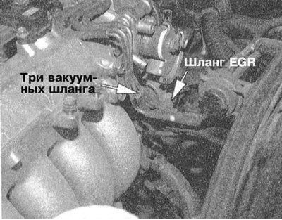
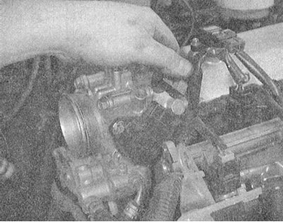
5. Disconnect all vacuum hoses and tubes interfering with the forthcoming procedure, including the lines of the vacuum brake booster and the PCV system. Disconnect the fuel supply and return lines.
 |  |
 | 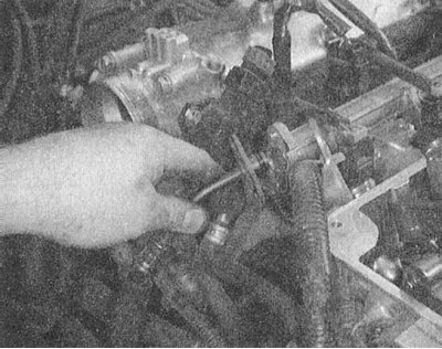 |
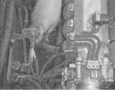
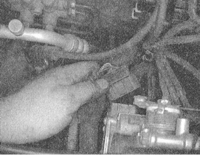
6. Remove the throttle cable guide brackets and move the cable aside.
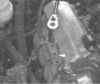 |  |
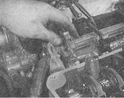
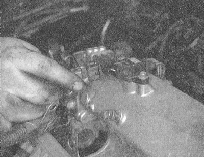
7. Tag and disconnect the wiring from the coolant temperature sensor and meter, IAC valve, ignition coil, EGR temperature sensor, knock sensor, oxygen sensor, TPS, air conditioning temperature sensor, other information sensors, fuel injection injectors, distributor, and power ignition transistor. Set aside the engine wiring harness.
 |  |
 |  |
 |  |
 | 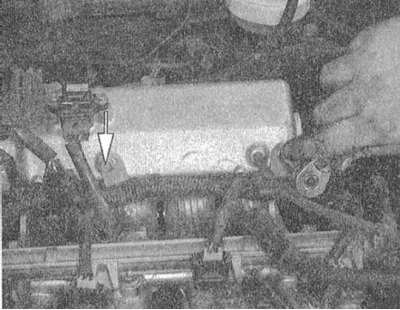 |
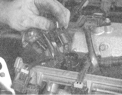
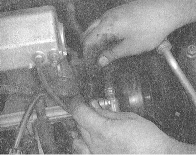
8. Having previously marked, disconnect the BB wiring from the spark plugs.
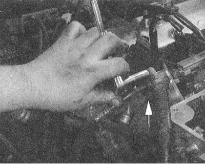
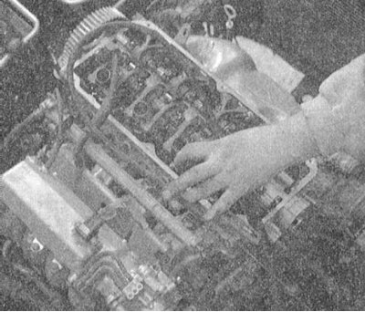
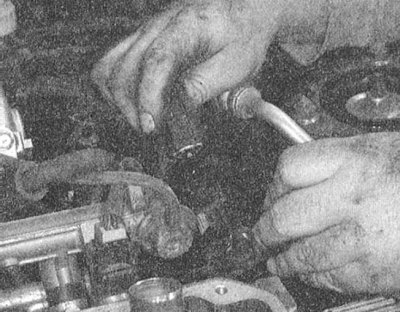
9. Remove the intake manifold support bracket.
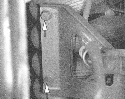
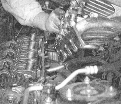
10. Turn out fixing bolts and remove assembly of the inlet pipeline. If necessary, transfer the pipeline to the workbench and disassemble it.
 |  |
Installation
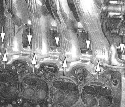
1. Thoroughly clean the mating surfaces of the intake manifold and cylinder head, completely removing traces of sealant and fragments of the old gasket material from them. Make sure that the water and air channels are passable - if necessary, clean them. Finally, wipe the mating surfaces with a rag soaked in acetone.
2. If necessary, after replacing the gaskets, assemble the pipeline.
3. Lay a new sealing gasket on the mating surface of the cylinder head, press the intake manifold assembly from above. Screw in the mounting bolts/nuts and, moving diagonally from the inside out, evenly tighten them to the required torque (20 Nm for bolts and 35 Nm for nuts on 1994 models, or 20 Nm for nuts on 1995 to 2000 models. issue).
4. Install the fuel line with injectors and pressure regulator on the engine. Screw in the mounting bolts and tighten them with the required force (6 Nm).
5. Install the intake manifold support bracket, screw in the mounting bolts and tighten them to the required torque (29 Nm).
6. Restore the original connection of all communication lines and wiring.
7. Fill the cooling system with the required amount of mixture of the required grade (see chapter Settings and ongoing maintenance).
8. Connect the negative cable to the battery, start the engine and warm it up to normal operating temperature (thermostat should work). Check the coolant level in the radiator, correct if necessary (see chapter Settings and ongoing maintenance).
9. Adjust the throttle cable, check the idle speed and ignition timing settings, make the necessary adjustments if necessary (see chapter Settings and ongoing maintenance).
10. Wait for the engine to cool down and check the coolant level again.
Engines 3.0 l and 3.5 l
Removing
1. The installation diagram of the intake manifold on 3.0 and 3.5 liter engines is shown in the illustrations.
2. Relieve pressure in the supply system (see chapter Power and exhaust systems).
Remember that gasoline is a highly flammable liquid! Observe all applicable fire safety precautions when working on power system components. Do not smoke! Do not approach the place of work with an open flame or carrying an unprotected lampshade! Do not service the system in rooms equipped with natural gas-fired heaters equipped with a pilot flame (such as water heaters and clothes dryers). Do not forget that gasoline is classified as a carcinogen, i.e., substances that contribute to the development of cancer! Try to avoid getting fuel on open areas of the body, use rubber protective gloves, in case of accidental unexpected contact with fuel, thoroughly wash your hands with warm water and soap. Clean up spilled fuel immediately and do not store fuel-soaked rags near open flames. Remember that the fuel injection system of models equipped with fuel injection is constantly under pressure. Relieve any residual pressure in the system before attempting to disconnect the fuel lines. Wear safety goggles when servicing power system components. Keep a class B fire extinguisher handy at all times!
3. Disconnect the negative cable from the battery.
If the stereo system installed in the car is equipped with a security code, before disconnecting the battery, make sure that you have the correct combination to activate the audio system! Empty the cooling system.
To avoid burns, proceed with this work only after the final cooling of the system! Do not allow antifreeze to come into contact with exposed areas of the body and painted surfaces of the car. Accidental splashes should be washed off immediately with plenty of water. Remember that antifreeze is a highly toxic liquid and getting it into the body, even in small quantities, is fraught with the most serious consequences (up to death). Never leave antifreeze stored in a loosely sealed container and clean up spilled coolant on the floor without delay. Remember that the sweet smell of antifreeze can attract the attention of children and animals. Consult any car service station about ways to dispose of used coolant. In many regions of the world, special points have been set up to receive various types of detention. Never drain old coolant down the drain and onto the ground!
4. Remove the intake duct (s).
5. Disconnect the throttle cable from the throttle body.
6. Mark and disconnect vacuum hoses, including a brake booster hose.
7. Mark and disconnect the interfering electrical wiring.
8. Disconnect the fuel supply and return lines. Remove the throttle cable guide brackets.
9. Disconnect the EGR tube and remove the EGR valve and EGR temperature sensor from the intake manifold pressure chamber assembly.
10. If equipped, remove the MAP sensor.
11. Remove the pressure chamber support bracket.
12. Give fixing bolts and nuts and remove the delivery chamber from the inlet pipeline. The gasket must be replaced without fail!
13. Remove the top timing cover.
14. Remove the water pump support bracket.
15. Remove the fuel line with injectors.
16. Disconnect the hoses of the cooling path from the inlet pipeline - try to remember the laying routes and the order of connecting the hoses.
17. Give fixing nuts and remove the inlet pipeline from the engine.
Installation
1. Thoroughly clean the mating surfaces of the intake manifold, discharge chamber and cylinder heads, completely removing traces of sealant and fragments of old gasket material from them. Make sure that the water and air channels are passable - if necessary, clean them. Finally, wipe the mating surfaces with a rag soaked in acetone.
2. Check the surfaces for cracks, evaluate the degree of their non-flatness (see Specifications). Replace defective components.
3. Lay new gaskets on the mating surfaces of the cylinder heads (adhesive side up).
4. Establish assemblage of the inlet pipeline on a regular place.
5. Lightly oil the studs and screw on the mounting nuts.
6. Tighten fasteners to the required torque (see Specifications).
7. Connect to the inlet pipeline hoses of a cooling path and fix them with new collars.
8. After replacing the O-rings, reinstall the fuel line assembly. Screw in the mounting bolts and tighten them with the required force (10÷13 Nm).
9. After replacing the gasket, install the injection chamber and tighten its fasteners (bolt/nuts) with the required force (18 Nm).
10. Install the support bracket and tighten the bolts of its fastening with the required force (18 Nm).
11. If removed, reinstall the MAP sensor.
12. After replacing the gasket, install the EGR valve, screw in the mounting bolts and tighten them with the required force (22 Nm).
13. Install the EGR temperature sensor and tighten its union connector with a force of 10÷12 Nm.
14. Connect the EGR pipe and tighten its union connectors with a force of 60 Nm.
15. After replacing the O-ring, connect the fuel supply pipe. Tighten the fixing bolts to the required torque (5 Nm).
16. Connect the fuel return line and secure it to the fitting with a new clamp.
17. Install the water pump support bracket.
18. Install the upper timing covers.
19. Restore the original wiring and vacuum hose connections.
20. Connect and adjust throttle cable.
21. Replace the intake duct (s).
22. Fill the cooling system with the required amount of mixture of the required grade (see chapter Settings and ongoing maintenance).
23. Connect the negative cable to the battery, start the engine and warm it up to normal operating temperature (thermostat should work). Check the coolant level in the radiator, correct if necessary (see chapter Settings and ongoing maintenance).
24. Check the idle speed and ignition timing settings, if necessary, make the necessary adjustments (see chapter Settings and ongoing maintenance).
25. Wait for the engine to cool down and check the coolant level again.