
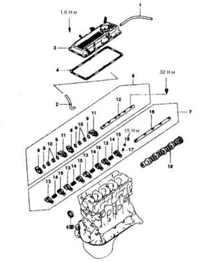
Valve actuator assembly components for 1.5L engines
1 - Breather pipe; 2 - PCV hose; 3 - Cylinder head cover; 4 - Sealing gasket; 5 - Oil seal; 6 - Assembling the valve drive; 7 - Assembling the valve drive; 8 - Rocker arms D; 9 - Wavy washer; 10 - Remote bushings; 11 - Rocker C; 12 - Axis of the rocker arms of the exhaust valve drive; 13 - Rocker B; 14 - Rocker springs; 15 - Rocker A; 16 - Axis of the rocker arms of the intake valve drive; 17 - Adjusting screw; 18 - Nut; 19 - Camshaft; N - replace
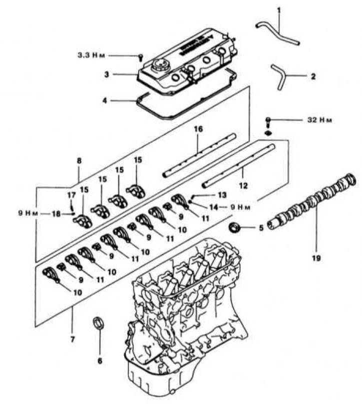
Valve actuator assembly components for 1.8L engines
1 - Breather pipe; 2 - PCV hose; 3 - Cylinder head cover; 4 - Sealing gasket; 5 - Oil seal; 6 - Oil seal; 7 - Assembling the valve drive; 8 - Assembling the valve drive; 9 - Springs of the axis of the rocker arms; 10 - Rocker A; 11 - Rocker B; 12 - Axis of the rocker arms of the intake valve drive; 13 - Adjusting screw; 14 - Nut; 15 - Rocker C; 16 - Axis of the rocker arms of the exhaust valve drive; 17 - Adjusting screw; 18 - Nut; 19 - Camshaft
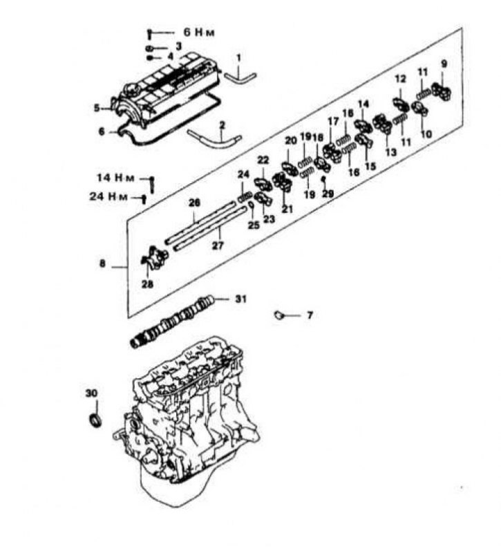
SOHC 2.0L Engine Valve Actuator Assembly Components
1 - Breather pipe; 2 - PCV hose; 3 - Gasket; 4 - Sealing sleeve; 5 - Cylinder head cover; 6 - Sealing gasket; 7 - Semi-ring seals; 8 - Assembling the valve drive; 9 - Rear bearing cover; 10 - Rocker arm D; 11 - Springs; 12 - Rocker arm D; 13 - Bearing cover No. 4; 14 - Rocker C; 15 - Rocker C; 16 - Spring; 17 - Bearing cap No. 3; 18 - Rocker D; 19 - Spring; 20 - Rocker D; 21 - Bearing cap No. 2; 22 - Rocker C; 23 - Rocker C; 24 - Spring; 25 - Wavy washer; 26 - The right axis of the rocker arms; 27 - Left axis of rocker arms; 28 - Front bearing cap; 29 - Valve clearance hydraulic corrector; 30 - Oil seal; 31 - Camshaft
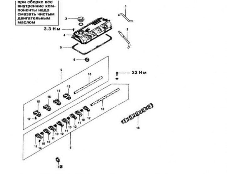
Valve actuator assembly components for 2.4L engines
1 - Breather pipe; 2 - PCV hose; 3 - Engine oil filler cap; 4 - Cylinder head cover; 5 - Sealing gasket; 6 - Oil seal; 7 - Oil seal; 8 - Assembling the valve drive; 9 - Assembling the valve drive; 10 - Springs; 11 - Rocker A; 12 - Rocker B; 13 - Axis of the rocker arms of the intake valve drive; 14 - Valve clearance hydraulic corrector; 15 - Rocker C; 16 - Axis of the rocker arms of the exhaust valve drive; 17 - Valve clearance hydraulic corrector; 18 - Camshaft; N - Replace
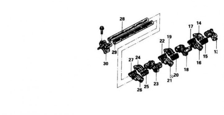
3.0L SOHC Valve Actuator Assembly Components
13 - Bearing cover; 14 - Rocker; 15 - Spring; 16 - Rocker; 17 - Spring; 18 - Bearing cap No. 3; 19 - Rocker; 20 - Spring; 21 - Rocker; 22 - Spring; 23 - Bearing cap No. 2; 24 - Rocker; 25 - Spring; 26 - Rocker; 27 - Spring; 28 - Axis of rocker arms; 29 - Axis of rocker arms; 30 - Bearing cap No. 1
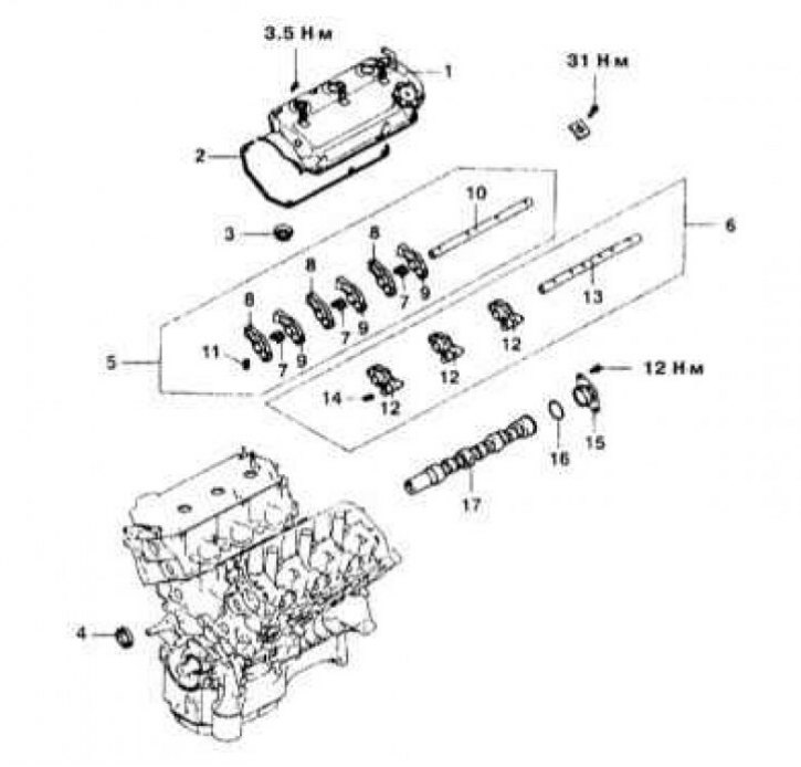
Valve actuator assembly components for 3.5L DOHC engines
1 - Cylinder head cover; 2 - Sealing gasket; 3 - Sealing sleeve; 4 - Camshaft seal; 5 - Assembling the valve drive; 6 - Assembling the valve drive; 7 - Springs; 8 - Rocker A; 9 - Rocker B; 10 - Axis of rocker arms; 11 - Valve clearance hydraulic corrector; 12 - Rocker C; 13 - Axis of rocker arms; 14 - Valve clearance hydraulic corrector; 15 - Thrust plate; 16 - O-ring; 17 - Camshaft
Engines 1.5 l and 1.8 l
Removing
1. Disconnect the negative cable from the battery.
If the stereo system installed in the car is equipped with a security code, before disconnecting the battery, make sure that you have the correct combination to activate the audio system!
2. On 1.8L models, mark and disconnect the BB wires from the spark plugs.
3. Disconnect the throttle cable, breather tube and PCV valve with hose connected to it.
4. Remove the cylinder head cover (see Section Removal and installation of a cover of a head of cylinders). The design of the valve drive assembly is shown in the illustrations.
5. In several stages, evenly loosen the fasteners and remove the axles with the rocker arms put on them from the engine.
6. If there is a need to remove the rocker arms from the axles, take care of the possibility of organized storage of components (during assembly, they must be installed strictly in their original places).
Installation
1. Lubricate the rocker shafts with clean engine oil and install the rocker arms and springs on them (strictly to their original places).
2. Install the axle assemblies with rocker arms in the engine and tighten the bolts of their fastening with the required force (32 H m).
3. Check the correct adjustment of the valve clearances, if necessary, make the appropriate adjustments, then install the cylinder head cover and tighten the bolts of its fastening with the required force (1.8 N·m - for 1.5 l engines and 3.3 N·m - for 1.8 l engines).
4. If removed, connect the BB wiring to the spark plugs.
5. Restore the original connection of the throttle cable, breather tube and PCV hose.
6. Connect the negative cable to the battery.
2.0L SOHC engines
Removing
1. On these engines, the valve rockers are equipped with hydraulic tappets. If necessary, the pusher can be removed from its seat in the rocker. The compilers of this Guide recommend replacing all pushers and valve clearance hydraulic correctors at the same time. The design of the valve drive assembly is shown in the illustration.
2. Disconnect the negative cable from the battery.
If the stereo system installed in the car is equipped with a security code, before disconnecting the battery, make sure that you have the correct combination to activate the audio system!
3. Remove the cylinder head cover.
4. Mark position of the case of the distributor of ignition in relation to a head of cylinders. Remove the distributor.
5. Remove the timing belt.
6. Moving outward from the center evenly in several steps in a diagonal manner, loosen the fasteners of the camshaft bearing caps.
7. Remove the axles of the rocker arms with the rocker arms put on them, complete with bearing caps - remember that during assembly, all components must be installed strictly in their original places and in their previous positions!
8. Dismantle the valve drive assembly, - start by removing the rear bearing cap, then move from one component to another in turn.
9. Check the condition and freedom of rotation of the rollers of the rocker arms, evaluate the degree of wear of the inner walls of the nests for the landing of the pushers. If necessary, replace the rocker arms.
Installation
1. Lightly grease the rear edges of the end bearing caps.
2. Insert the assemblies into the front bearing cap (axes up). Screw in but do not tighten the set bolt yet.
3. Screw in the bolts of the remaining bearing caps and evenly tighten them to the required torque (20 Nm). Remove the valve clearance adjuster holders.
4. Install the timing belt.
5. Reinstall the ignition distributor, - make sure that the landing marks applied during the dismantling process are aligned correctly.
6. Remove the fixtures fixing the hydraulic corrector assemblies.
7. Reinstall the cylinder head cover - do not forget to replace the gasket and semi-ring seals.
8. Connect the negative cable to the battery.
9. Start the engine and check that the ignition timing is set correctly and correct if necessary (see chapter Settings and ongoing maintenance).
1.6L and 2.0L DOHC engines (turbocharged and non-turbocharged)
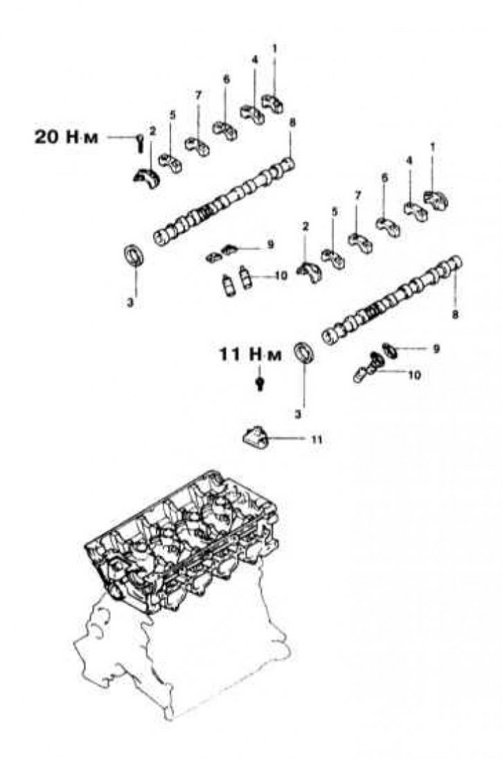
Valve actuator assembly components for 1.6L and 2.0L DOHC engines
1 - Rear bearing cover; 2 - Front bearing cover; 3 - Camshaft seal; 4 - Bearing cover No. 5; 5 - Bearing cover No. 2; 6 - Bearing cover No. 4; 7 - Bearing cover No. 3; 8 - Camshaft; 9 - Rocker; 10 - Valve clearance hydraulic corrector; 11 - Oil distributor housing
Removing
1. The design of the valve train actuator for 1.6L and 2.0L DOHC engines is shown in the illustration.
2. Disconnect the negative cable from the battery.
If the stereo system installed in the car is equipped with a security code, before disconnecting the battery, make sure that you have the correct combination to activate the audio system!
3. Remove the cylinder head cover and gasket (the latter must be replaced without fail).
4. Install fixtures for fixing valve clearance hydraulic correctors (MD998443 or equivalent).
5. In several stages, evenly loosen and unscrew the clamping bolts for fixing the valve drive assembly and remove the latter from the engine. If it is necessary to dismantle the assembly, take care to ensure that the removed components can be stored in an organized manner.
6. Check the condition and freedom of rotation of the rollers of the rocker arms, evaluate the degree of wear of the inner walls of the sockets for the landing of the pushers. If necessary, replace the entire set of rocker arms.
Installation
1. Having previously lubricated the components, mount the valve drive assembly by installing the rocker arms and springs in their regular places.
2. Install the assembly on the engine and tighten the mounting bolts evenly in several steps to the required torque (29÷35 H m).
3. Remove the tools used to fix the hydraulic correctors.
4. Replace the cylinder head cover (don't forget to replace the gasket).
5. Connect the negative cable to the battery.
Engines 2.4 l
Removing
1. The design of the valve mechanism drive for 2.4 l engines is shown in the illustration.
2. Disconnect the negative cable from the battery.
If the stereo system installed in the car is equipped with a security code, before disconnecting the battery, make sure that you have the correct combination to activate the audio system!
3. Release from fixing clips and take aside the throttle cable.
4. Remove the air intake sleeve.
5. Disconnect the breather tube and PCV hose.
6. Disconnect the BB wires from the spark plugs.
7. Remove the cylinder head cover with gasket.
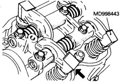
8. Install fixtures for fixing valve clearance hydraulic correctors (MD998443 or equivalent).
9. In several stages, evenly loosen and unscrew the clamping bolts for fixing the valve drive assembly and remove the latter from the engine. If it is necessary to dismantle the assembly, take care to ensure that the removed components can be stored in an organized manner.
10. Check the condition and freedom of rotation of the rollers of the rocker arms, evaluate the degree of wear of the inner walls of the sockets for the landing of the pushers. If necessary, replace the entire set of rocker arms.
Installation
1. Immerse the valve clearance hydraulic corrector assemblies in clean diesel fuel and fill them, completely removing air: use a wire to move the plunger up and down four to five times while slightly pressing the control ball (repeat the procedure for each of the pushers).
2. Put the pushers each in their own rocker and fix them with a special tool.
3. Lubricate the axles with clean engine oil and fit the rocker arms on them.
4. Temporarily tighten the axle mounting bolts so that the rocker arms of all inlet valves do not press the latter.
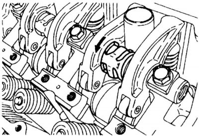
5. Place the axle springs on top, placing them at right angles to the plug. Seat the springs before installing the exhaust valve actuator assembly.
6. Place the exhaust valve drive assembly into the engine, screw it in and evenly, in several steps, tighten the bolts of its fastening with the required force (32 Nm).
7. Remove the fixing assemblies of the hydraulic correctors of the device.
8. Reinstall the cylinder head cover and tighten the bolts of its fastening with a force of 3 Nm.
9. Connect the BB wires to the spark plugs.
10. Connect the PCV hose and breather tube to the cylinder head cover.
11. Replace the air intake sleeve.
12. Restore the original gasket and throttle cable connection.
13. Connect the negative cable to the battery.
3.0L SOHC engines
Removing
1. On these engines, the rocker arms of the valve drive are also equipped with hydraulic correctors.
2. Disconnect the negative cable from the battery.
If the stereo system installed in the car is equipped with a security code, before disconnecting the battery, make sure that you have the correct combination to activate the audio system!
3. Remove the cylinder head cover.
4. Install fixtures for fixing valve clearance hydraulic correctors (MD998443 or equivalent).
5. In several stages, evenly loosen and unscrew the clamping bolts for fixing the valve drive assembly and remove the latter from the engine. If it is necessary to dismantle the assembly, take care to ensure that the removed components can be stored in an organized manner.
6. Remove the cover of the rear camshaft bearing, then remove the valve drive rocker arm, springs and washers from the axis of the rocker arm - follow the organization of the storage of the removed components.
7. Assess the condition and degree of wear of the components, if necessary, replace the entire set of rocker arms.
Installation
1. Immerse the assemblies of the valve clearance hydraulic correctors in clean diesel fuel and fill them, completely removing the air: using a wire, move the plunger up and down four or five times while lightly pressing the control ball (repeat the procedure for each of the pushers).
2. Put the pushers each in their own rocker and fix them with a special tool.
3. Lubricate the axles with clean engine oil and fit the rocker arms on them.
4. Lay assembly of a drive of valves in a head of cylinders.
5. Lightly grease the rear edges of the end bearing caps with sealant.
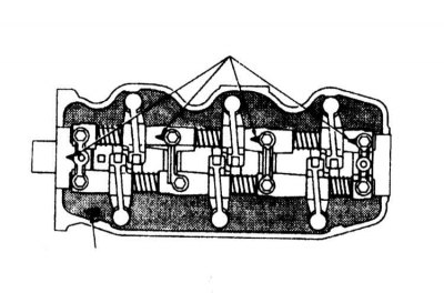
6. Make sure that the rocker shafts are turned with the risks up, then install the bearing caps (make sure they are oriented correctly), screw in and in several stages evenly tighten to the required torque (20 Nm) their mounting bolts.
7. Remove the fixing assemblies of the hydraulic correctors of the device.
8. Reinstall the cylinder head cover.
9. Connect the negative cable to the battery.
3.0L DOHC engines
Remember that gasoline is a highly flammable liquid! Observe all applicable fire safety precautions when working on power system components. Do not smoke! Do not approach the place of work with an open flame or carrying an unprotected lampshade! Do not service the system in rooms equipped with natural gas-fired heaters equipped with a pilot flame (such as water heaters and clothes dryers). Do not forget that gasoline is classified as a carcinogen, i.e., substances that contribute to the development of cancer! Try to avoid getting fuel on open areas of the body, use rubber protective gloves, in case of accidental unexpected contact with fuel, thoroughly wash your hands with warm water and soap. Clean up spilled fuel immediately and do not store fuel-soaked rags near open flames. Remember that the fuel injection system of models equipped with fuel injection is constantly under pressure. Relieve any residual pressure in the system before attempting to disconnect the fuel lines. Wear safety goggles when servicing power system components. Keep a class B fire extinguisher handy at all times!
Removing
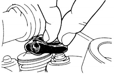
1. On these engines, the rocker arms of the valve drive are planted directly under the camshaft and rest with one end on the ends of the valve stems, and with the other end on the hydraulic corrector assemblies.
2. Disconnect the negative cable from the battery.
If the stereo system installed in the car is equipped with a security code, before disconnecting the battery, make sure that you have the correct combination to activate the audio system!
3. Remove the timing cover and timing belt (see Section Removing and installing timing cover and timing belt).
4. Remove the center cap, breather tube and PCV hose. Disconnect the spark plug wires.
5. Remove the cylinder head cover.
6. Remove the throttle body strut, gears and oil seals on both camshafts.
7. Remove the camshaft position sensor from the rear of the camshaft (SMR) with nozzle.
8. Remove the intake and exhaust camshafts.
9. Remove the rocker arms of the valve drive and hydraulic correctors, assess the degree of wear of the components, if necessary, replace the entire set.
Installation
1. Immerse the valve clearance hydraulic corrector assemblies in clean diesel fuel and fill them, completely removing air: use a wire to move the plunger up and down four to five times while slightly pressing the control ball (repeat the procedure for each of the pushers).
2. Lubricate the valve clearance adjusters and install them in their seats in the cylinder head.
3. Grease camshafts and lay them in a head of cylinders.
4. Install the bearing caps, screw in the mounting bolts and tighten them evenly in two or three steps. The covers of the 2nd, 3rd and 4th bearings are equipped with markings applied to their front part - make sure that the marks are aligned with the mating marks applied to the surface of the head. On the covers of the inlet shaft, marks are stamped in the form of the letter I, exhaust - E. Also, make sure that the rocker arms are properly seated on the assemblies of hydraulic correctors and valve stem shanks. The bolts of the front and rear bearing caps are tightened with a force of 20 Nm, the central one - 11 Nm.
5. Install the camshaft seals after lubricating them with clean engine oil.
6. Install timing belt (see Section Removing and installing timing cover and timing belt), cylinder head cover and all other components that have been removed for access.
7. Connect the negative cable to the battery, start the engine and check for signs of leaks.
Engines 3.5 l
Removing
1. The design of the valve actuator used on these engines is shown in the illustration.
2. Disconnect the negative cable from the battery.
If the stereo system installed in the car is equipped with a security code, before disconnecting the battery, make sure that you have the correct combination to activate the audio system!
3. Remove the cylinder head cover.
4. Use special clamps to fix the valve clearance hydraulic corrector assemblies in the rocker arms, then release (but don't twist) bearing cap bolts.
5. Remove rocker shafts complete with rocker arms and bearing caps.
6. Assess the degree of wear of the components, if necessary, replace.
Installation
1. Install valve actuator assembly with bearing caps. Tighten the fixing bolts to the required torque (31 Nm).
2. Remove the clips that secure the hydraulic correctors in the rocker arm sockets.
3. Install the cylinder head cover (don't forget to replace the gasket).
4. Connect the negative cable to the battery.