
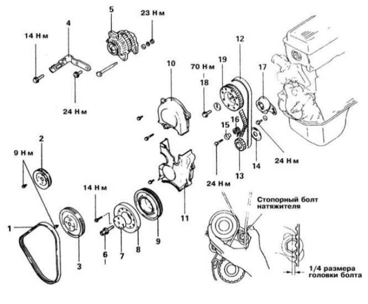
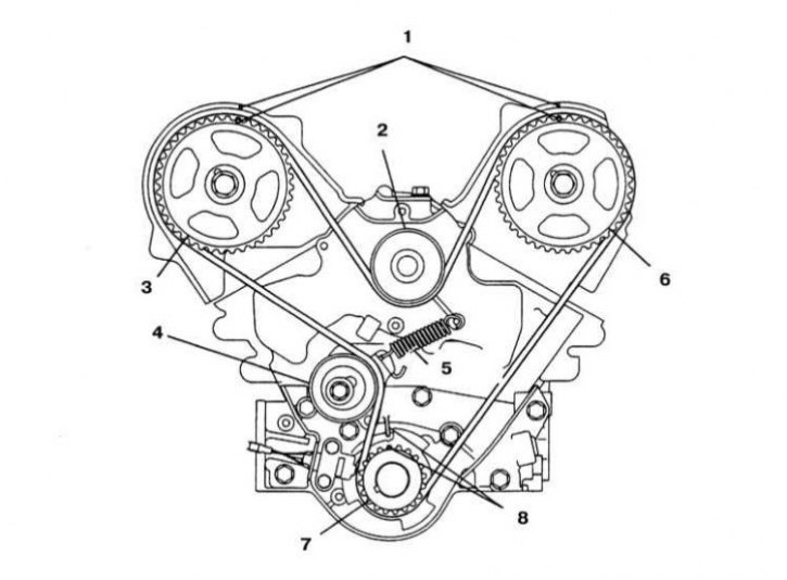
Installation details of the cover and timing drive components on 1.5 l models 1990÷1994. issue
1 - Drive belt; 2 - Steering pump pulley; 3 - Water pump pulley; 4 - Generator support bracket; 5 - Generator; 6 - Central bolt of the crankshaft pulley; 7 - Washer; 8 - Crankshaft pulley; 9 - Damper pulley; 10 - Upper section of the front cover; 11 - Lower section of the front cover; 12 - Gas distribution belt; 13 - Crankshaft gear; 14 - Flange; 15 - Remote tensioner bushing; 16 - Tensioner spring; 17 - Tensioner; 18 - Bolt; 19 - Camshaft gear
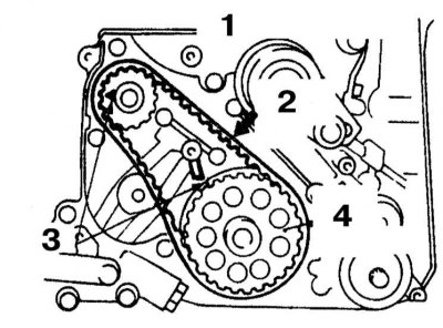
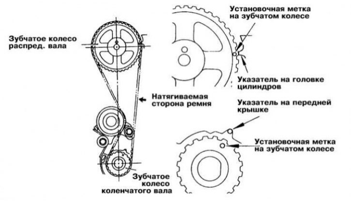
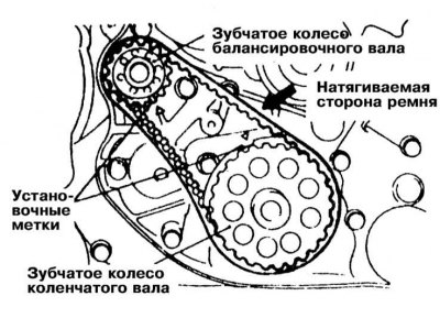
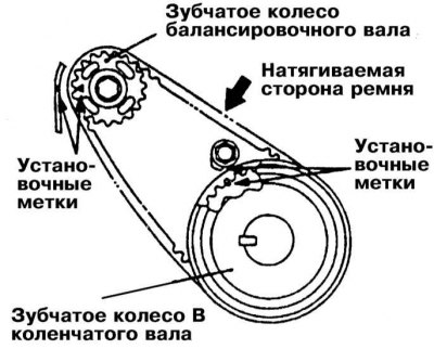
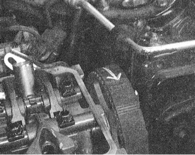
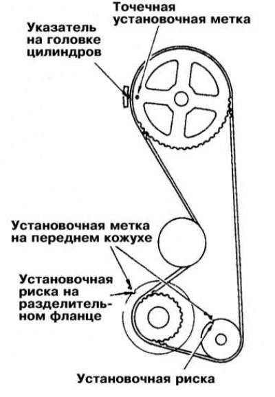
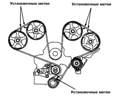
Location of balancing shaft alignment marks on 2.4 l models
1 - Gear wheel of the balancing shaft; 2 - Tensioned side of the belt; 3 - Setting mark; 4 - Gear B of the crankshaft
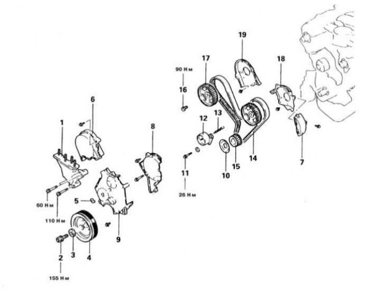
Timing Cover and Component Installation Details on 3.0L Models (SOHC) 1990÷1994 issue
1 - Bracket of the suspension support of the power unit; 2 - Bolt; 3 - Washer; 4 - Crankshaft pulley; 5 - Access cover; 6 - Right upper section of the front cover of the timing drive; 7 - Cover; 8 - Left upper section of the front timing cover; 9 - Lower section of the front cover of the timing drive; 10 - Flange; 11 - Locking bolt; 12 - Tensioner; 13 - Tensioner spring; 14 - Gas distribution belt; 15 - Crankshaft gear; 16 - Bolt; 17 - Camshaft gear; 18 - Left section of the rear timing cover; 19 - Right section of the rear timing cover
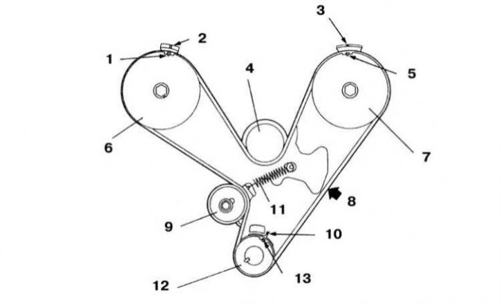
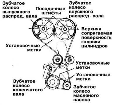
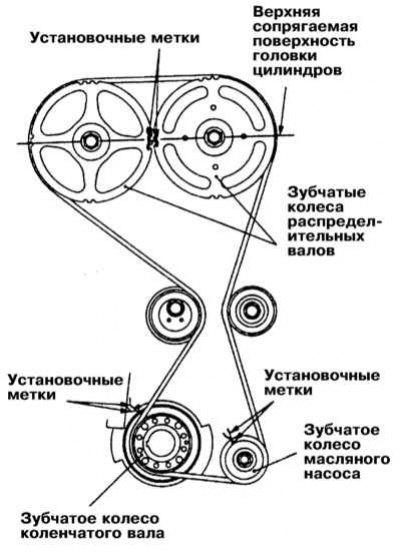
The location of the alignment marks of the gears of the timing drive for 3.0 l models (SOHC) 1992÷1994 issue
1 - Setting mark; 2 - Pointer on the rear cover or generator support bracket; 3 - Mounting mark on the cover; 4 - Water pump pulley; 5 - Setting mark; 6 - Gear wheel of the right camshaft; 7 - Gear wheel of the left camshaft; 8 - Tensioned side of the belt; 9 - Tensioner; 10 - Mounting mark on the front casing; 11 - Tensioner spring; 12 - Crankshaft gear; 13 - Setting mark
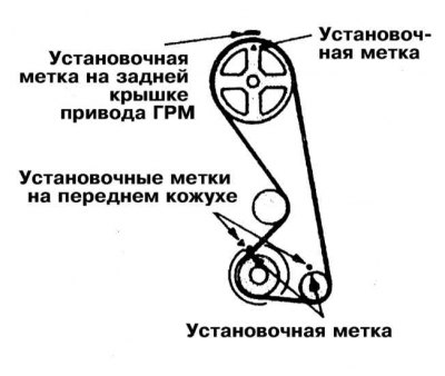
The location of the alignment marks of the gear wheels of the timing drive on the Diamante models 1995÷1996. ed., equipped with a 3.0 l SOHC engine (6G72)
1 - Mounting marks on the drive cover; 2 - Water pump drive roller; 3 - Gear wheel of the right camshaft; 4 - Belt tensioner; 5 - Tensioner spring; 6 - Gear wheel of the left camshaft; 7 - Crankshaft gear; 8 - Setting marks
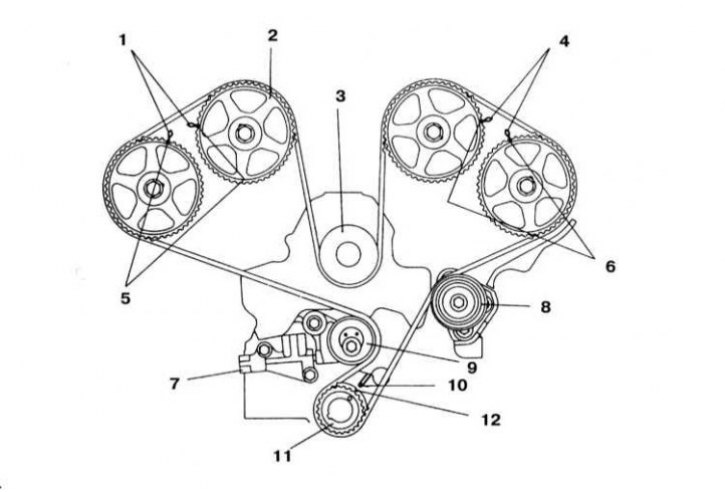
The location of the timing marks of the gear wheels of the timing drive on Mitsubishi cars 1992÷1994. ed., equipped with a 3.0 l DOHC engine
1 - Mounting marks on the cover of the right cylinder head; 2 - Camshaft gear; 3 - Water pump drive roller; 4 - Mounting marks on the cover of the left cylinder head; 5 - Mounting marks; 6 - Mounting marks; 7 - Automatic tensioner; 8 - Intermediate roller; 9 - Tensioner roller; 10 - Mounting mark on the oil pump housing; 11 - Crankshaft gear; 12 - Setting mark
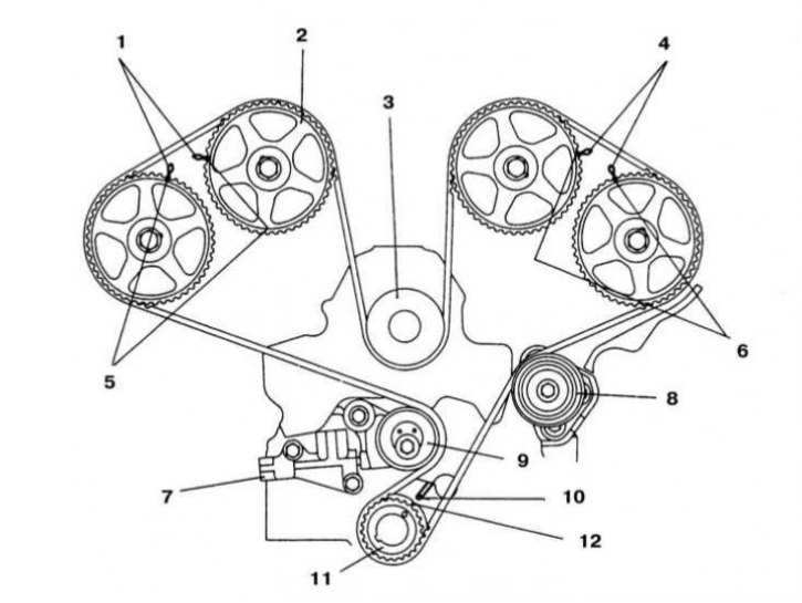
The location of the alignment marks of the timing gears on the Diamante models 1995 and 1996 ed., equipped with a 3.0 l DOHC engine (6G72)
1 - Mounting marks on the cover of the right cylinder head; 2 - Camshaft gear; 3 - Water pump drive roller; 4 - Mounting marks on the cover of the left cylinder head; 5 - Mounting marks; 6 - Mounting marks; 7 - Automatic tensioner; 8 - Intermediate roller; 9 - Tensioner roller; 10 - Mounting mark on the oil pump housing; 11 - Crankshaft gear; 12 - Setting mark
The description of the procedure for servicing the gas distribution belt is given in Chapter Settings and ongoing maintenance.
Engines 1.5 l
Models 1990÷1994 issue
Removing
1. Installation details of the cover and timing drive components on 1.5 l models 1990÷1994. issue shown in the illustration.
2. Disconnect the negative cable from the battery.
If the stereo system installed in the car is equipped with a security code, before disconnecting the battery, make sure that you have the correct combination to activate the audio system!
3. Remove the crankcase protection elements.
4. Support the engine with a trolley jack (in order to distribute the load, lay a block of wood between the head of the jack and the engine sump). Remove the accessory drive belts.
5. If necessary, remove the expansion tank of the cooling system.
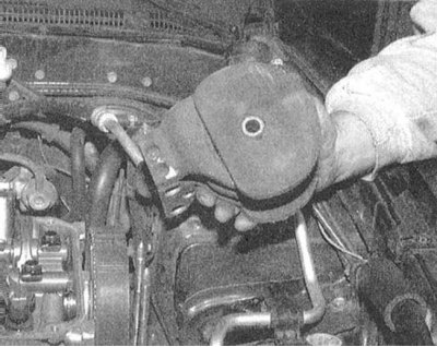
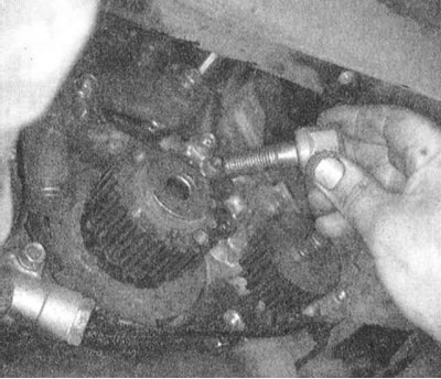
6. Slightly raise the engine on a jack and remove the bracket of the front support of the power unit. Remove the tensioner brackets and the water pump and crankshaft pulleys.
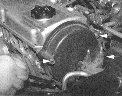
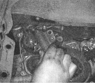
7. Turn out fixing screws and remove the top and bottom sections of a forward cover of a drive GRM.
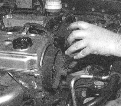
8. Mark the direction of rotation of the timing belt with chalk or paint, loosen the tensioner and remove the belt.
Try not to let coolant or engine oil get on the surface of the timing belt or timing gears!
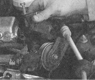
9. Remove spacer, spring and tensioner assembly.
10. Carefully inspect the belt from all sides for cracks, abrasions, traces of oil contamination and other defects. Manually evaluate the freedom of rotation of the idler roller.
Installation
1. Install the tensioner assembly with spring and spacer on the engine block.
2. Achieve the correct alignment of the alignment marks of the gear wheels of the camshaft and crankshaft, which should ensure that the engine is brought to the TDC position of the end of the compression stroke of the piston of the first cylinder.
3. Keeping the appropriate side of the belt taut, slide it over the camshaft and crankshaft gears.
4. To tension the belt, apply force to the camshaft gear in a counterclockwise direction and make sure that the alignment marks are aligned correctly.
5. Release the axial and locking bolts of the tensioner - the slack in the belt should get out due to the force developed by the tensioner spring.
6. Tighten first the lock, then the axial bolts of the tensioner.
Tightening the axle bolt first can cause the tensioner to unfold and thus loosen the belt!
7. Turn the crankshaft clockwise. Loosen the tensioner axle bolts first, then the tensioner lock bolts, allowing the spring to take up the remaining slack in the belt. Retighten the bolts in the correct order (see above), - this time with the required force (20÷27 Nm).
8. Check the correct tension of the belt, for which, while holding the tension roller, press the straight run of the belt in the middle with your thumb - when firmly pressed, the belt should bend by an amount approximately equal to 1/4 of the size of the head of the locking bolt (see ibid).
Remember that overtightening the belt can cause a howling sound when the engine is running!
9. Reinstall the timing covers and all other components removed for access.
10. Connect the negative cable to the battery.
Models 1995÷2000 issue
Removing
1. Disconnect the negative cable from the battery.
If the stereo system installed in the car is equipped with a security code, before disconnecting the battery, make sure that you have the correct combination to activate the audio system!
2. Remove the crankcase protection elements.
3. After turning the engine clockwise, bring it to the TDC position of the end of the compression stroke of the piston of the first cylinder.
4. Support the engine with a trolley jack (in order to distribute the load, lay a block of wood between the head of the jack and the engine sump). Remove the A/C retainer, power unit front support bracket and accessory drive belts.
5. Remove the crankshaft pulley.
6. Turn out fixing screws and remove the top and lower sections of a forward cover of a GRM drive.
7. Chalk or paint mark the direction of rotation of the timing belt. Loosen the tensioner and lock it in this position.
8. Remove the belt.
Try not to let coolant or engine oil get on the surface of the timing belt or timing gears!
9. If necessary, remove the spacer bushing, spring and tensioner assembly.
10. Carefully inspect the belt from all sides for cracks, abrasions, traces of oil contamination and other defects. Manually evaluate the freedom of rotation of the idler roller.
11. Install the tensioner assembly with spring and spacer on the engine block.

12. Achieve the correct alignment of the alignment marks of the gear wheels of the camshaft and crankshaft, which should ensure that the engine is brought to the TDC position of the end of the compression stroke of the piston of the first cylinder.
13. Keeping the corresponding side of the belt taut, put it on the gears of the camshaft and crankshaft.
14. To tension the belt, apply force to the camshaft gear in a counterclockwise direction and make sure that the alignment marks are aligned correctly.
15. Release the axial and locking bolts of the tensioner - the slack in the belt should get out due to the force developed by the tensioner spring.
16. Tighten first the lock, then the axial bolts of the tensioner.
Tightening the axle bolt first can cause the tensioner to unfold and thus loosen the belt!
17. Turn the crankshaft clockwise. Loosen the tensioner axle bolts first, then the tensioner lock bolts, allowing the spring to take up the remaining slack in the belt. Retighten the bolts in the correct order (see above), - this time with the required force (24 Nm).
18. Replace the timing cover, screw in the mounting bolts and tighten them with the required force (10÷11 Nm).
19. Install all other components removed for access.
20. Connect the negative wire to the battery.
Naturally aspirated 1.6L and 2.0L DOHC engines
There are no balancing shafts on 1.6 liter engines - the corresponding instructions should be omitted.
Removing
1. Disconnect the negative cable from the battery.
If the stereo system installed in the car is equipped with a security code, before disconnecting the battery, make sure that you have the correct combination to activate the audio system!
2. Remove the crankcase protection elements.
3. If necessary, remove the expansion tank of the cooling system.
4. Support the engine with a trolley jack (in order to distribute the load, lay a block of wood between the head of the jack and the engine sump) and remove the powertrain support bracket.
5. Remove the accessory drive belts, tensioner brackets, and water pump and crankshaft pulleys.
6. Turn out fixing screws and remove the top and lower sections of a forward cover of a GRM drive.
7. Turning the engine clockwise, bring it to the TDC position of the end of the compression stroke of the piston of the first cylinder, - the gears of the camshafts should turn with the mounting pins up (alignment marks will be at the level of the mating surface of the cylinder head). Chalk or paint mark the direction of rotation of the timing belt.
8. Remove the auto tensioner and outer gear (gas distribution) belt.
9. Remove tensioner pulley and arm, idler pulley, oil pump gear, special washer, flange and spacer.
10. Remove the internal tensioner of the internal toothed belt of the balancing shaft drive. Then remove the belt.
Installation
1. Achieve the correct alignment of the timing marks of the gears of the crankshaft and balancing shaft, then install the toothed belt of the balance shaft drive (interior).
2. While holding the tensioner with your fingers, press the belt down the center, taking up all the slack, then tighten the tensioner bolt.
3. Check that the belt tension is correctly adjusted: with firm pressure on the middle part of the longest run, the amount of deflection should be approximately 5÷7 mm. Repeat the adjustment if necessary.
4. Place the flange, timing belt gear and washer on the crankshaft trunnion.
The flange is installed on the gear side of the internal toothed belt. Screw in the fixing bolt and tighten it to the required torque (110÷130 Nm).
5. To install the gear wheel of the oil pump, insert a Phillips screwdriver with a sting with a diameter of 8 mm into a special hole in the left wall of the cylinder block (remove the plug first). Having blocked the balancing shaft with a screwdriver, tighten the fixing nut with the required force (50÷60 Nm).
6. Using an open-end wrench, put on the flats provided between the necks of the 2nd and 3rd bearings, fix the camshaft from turning and tighten the bolt of its gear wheel with the required force (80÷100 Nm).
If there are no flats between the journals of these bearings, the gear wheel can be locked with a fork wrench.
7. Carefully press the auto-tensioner rod inward so that the mounting hole in it is aligned with the hole in the cylinder block. To fix the stem, thread the wire through the hole.
8. Place the roller on the tensioner arm. Make sure that the pin hole in the idler shaft is to the left of the central bolt and hand-tighten the latter.
9. When installing the timing belt, turn the gears of the camshafts with the mounting pins up and the alignment marks to each other (the marks should be at the level of the mating surface of the head).
When the exhaust camshaft sprocket is released, it will turn one tooth counterclockwise, which must be taken into account when fitting the belt!
On the gear wheels of the camshafts, there is a sensor-switch of the alignment marks. When installing the exhaust shaft wheel, you should focus on the mark located on the right at the top position of the pin, when installing the intake shaft wheel, on the mark located on the left (the pin is also at the top).
10. Get the timing marks of the crankshaft and oil pump gears aligned correctly.
11. Remove the plug and insert a Phillips screwdriver with a 8 mm blade into the hole in the cylinder block wall - if the screwdriver is inserted approximately 60 mm, then the balancing shaft is in the correct position. If you manage to insert the screwdriver no deeper than 20÷25 mm, turn the oil pump gear one full turn and try again. Leave the screwdriver inserted into the hole.
Violation of the correct position of the balancing shaft is fraught with the development of vibrations during engine operation.
12. Throw a gear belt on a gear wheel of an inlet camshaft and fix it with two spring clips.
13. Get a belt on a gear wheel of a final camshaft, - by means of two keys achieve the correct alignment of adjusting marks. To fix the belt, use a pair of clips again.
14. Thread the belt under the intermediate roller, then pull it over the gears of the oil pump and crankshaft, finally tucking it under the tensioner roller. Remove clamps.
15. Turn the tensioner clockwise and tighten the center bolt. Make sure that the alignment marks are correctly aligned.
16. Turn the crankshaft 1/4 turn counterclockwise, then return it to its original position, having achieved the required combination of all installation marks, the engine should be in the TDC position of the end of the compression stroke of the piston of the first cylinder.
17 Loosen the center bolt, then use tool MD998738 and a torque wrench to torque the tensioner to 2.6÷2.8 Nm and retighten the bolt.
18 Screw the special tool into the left power unit support bracket until it is pressed against the tensioner arm. Screw in the tool a little more and remove the wire that secures the auto-tensioner. Remove the special tool.
19 Rotate the crankshaft two full turns clockwise, allow the components to seat for about 15 minutes, then measure the protrusion of the auto-tensioner (distance between tensioner arm and auto tensioner housing). The required value is 3.8÷4.5 mm. Repeat the adjustment if necessary.
20 If the timing belt tension is adjusted with the engine installed on the vehicle, it is not possible to measure the specified clearance. In this situation, you should resort to an alternative method:
- Screw in the tool MD998738, pressing its end against the tensioner lever;
- Screw in the tool a little more, sinking the tensioner pusher, count the number of turns of the tool required for the tensioner lever to press against the body of the automatic tensioner - the nominal value is 2.5÷3 turns;
- Install the rubber plug in the rear timing cover.
21 Install the front cover sections and other components removed for access.
22 Connect the negative cable to the battery.
1.8L and 2.0L SOHC engines
Removing
1. Bring the engine to the TDC position of the end of the compression stroke of the piston of the first cylinder.
2. Disconnect the negative cable from the battery.
If the stereo system installed in the car is equipped with a security code, before disconnecting the battery, make sure that you have the correct combination to activate the audio system!
3. Remove the crankcase protection elements.
4. Support the engine with a trolley jack (in order to distribute the load, lay a block of wood between the head of the jack and the engine sump). Remove the powertrain mount bracket.
5. Remove the accessory drive belts, idler pulley brackets, and water pump and crankshaft pulleys.
6. Turn out fixing screws and remove the top and lower sections of a forward cover of a GRM drive.
7. Remove the timing belt, crankshaft outer gear and spacer flange.
8. Remove the balancer shaft timing belt tensioner, then the inner belt itself.
9. Remove the crankshaft pulley.
10. Mark the direction of rotation of the timing belt with chalk or paint. Loosen the tensioner and lock it in this position.
Installation
1. Achieve the correct alignment of the alignment marks of the gears of the balancing and crankshafts with the mating marks on the front casing.
2. Slide the belt over the gears so that the top of the belt is taut. Check that the alignment marks are correctly aligned.
3. Install the tensioner and slide it by hand so that the long run of the belt sags by approximately 6 mm.
4. After blocking the pulley from turning, tighten the fixing bolt to the required torque (20 Nm) and recheck the deflection.
5. Pull the timing belt tensioner all the way towards the water pump and tighten the bolts. Press the top end of the spring against the water pump housing.
6. Get alignment marks on the camshaft, crankshaft and oil pump gears aligned with the match marks on the front casing.
There is a 50% chance that the balance shaft is incorrectly installed (180 degree offset) despite the correct alignment of all marks, which will lead to a noticeable increase in the level of vibrations during engine operation. In order to avoid such a situation, try to be very attentive to the implementation of the procedures listed below!
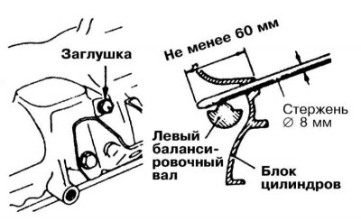
7. Before installing the timing belt, make sure that the left (rear) balance shaft (oil pump gear):
- Remove the plug from the rear wall of the cylinder block and insert a rod with a diameter of 8 mm into the opened hole;
- With the correct alignment of the marks, the rod should enter to a depth of about 60 mm. If it is not possible to insert the rod deeper than 25 mm, the oil pump gear should be turned one full turn;
- Make sure that the labels are aligned correctly;
- Leave the rod inserted into the hole to fix the balance shaft.
8. Put the belt on the gears, first the crankshaft, then the oil pump - make sure that all the slack is on the tensioner side.
9. Make sure that the alignment marks are correctly aligned. If everything is in order, loosen the tensioner mounting bolt, allowing the latter to take up the slack in the belt.
10. Remove the pin that fixes the balancing shaft and turn the crankshaft so that the camshaft gear has advanced two teeth, while the tensioner will automatically adjust the belt tension.
Attempts to manually adjust the belt are fraught with a howling sound when the engine is running!
11. Tighten first the bottom, then the top fixing/remote bolts.
12. Check the correct adjustment of the belt tension force - the amount of deflection of its longest run when firmly pressed with your thumb should be about 13 mm.
13. Installation of the timing cover and other components removed for access is carried out in the reverse order of their dismantling. Make sure that all the prescribed sealing elements are seated in the groove on the mating surfaces of the covers.
14. Connect the negative cable to the battery.
2.0L DOHC turbocharged engines
Removing
1. Disconnect the negative cable from the battery.
If the stereo system installed in the car is equipped with a security code, before disconnecting the battery, make sure that you have the correct combination to activate the audio system!
2. Remove the crankcase protection elements.
3. Support the engine with a trolley jack (in order to distribute the load, lay a block of wood between the head of the jack and the engine sump). Remove the powertrain mount bracket.
4. Remove the accessory drive belts.
5. Remove the drive belt tensioner.
6. Remove the water pump and crankshaft pulleys.
7. Remove the threaded stud from the powertrain suspension support bracket and remove the timing covers.
8. Turn the engine clockwise until the alignment marks are aligned.
9. Release the central bolt of the tension roller.
10. Mark the direction of rotation of the timing belt with chalk or paint. Move the tensioner towards the water pump and remove the belt.
11. Using the special tool MB9g67, block the crankshaft gear from turning and release the central bolt of its fastening. Using the MB998778 puller, remove the gear wheel.
12. Chalk or paint mark the direction of rotation of the toothed belt B.
13. Release the central tensioner bolt and remove the belt.
Installation
1. Place the gear wheel on the crankshaft trunnion, block it from turning with the MB9g67 tool and tighten the central fixing bolt with the required force (108÷127 Nm).
2. Achieve the correct alignment of the alignment marks on the gear B of the crankshaft and the balancing shaft wheel.
3. Put on the gear wheels the inner belt B. Take the tension roller to the left, placing it in the center above the fixing bolt.
4. Having turned the roller clockwise towards the crankshaft, select the slack in the belt and tighten the fixing bolt with a force of 19 Nm, - in order to avoid excessive belt tension, try to prevent the roller from moving during the tightening of the bolt. With the correct tension adjustment, the belt should sag approximately 5-7 mm when firmly pressed with the thumb in the area in the middle between the gears.
5. Install the crankshaft outer gear. Lightly lubricate the fixing bolt with oil, screw it in and tighten with a force of 108÷127 Nm.
6. Use a vise to depress the pusher of the automatic tensioner and fix it in this position by inserting a special finger into the aligned holes.
7. Install the auto-tensioner assembly to the engine.
8. Achieve the correct alignment of the alignment marks of the gears of the camshafts and crankshafts and the oil pump.
9. After the oil pump gear mark is correctly aligned, remove the plug from the cylinder block wall and insert a rod with a diameter of about 8 mm into the freed hole, the rod must enter the hole at least 60 mm, otherwise the pump gear should be turned one times and insert the rod again. Leave the rod inserted into the hole until the belt installation procedure is complete.
10. Put the timing belt on the gear wheel of the intake camshaft and fix it with a clip.
11. Put on a belt a gear wheel of a final camshaft.
12. Check up correctness of an arrangement of adjusting labels concerning an interfaced surface of a head of cylinders, - in case of need make corresponding adjustment by means of couple of wrenches. Secure the belt to the second wheel with another clip.
13. Get the belt under the intermediate roller, then pull it over the gears of the oil pump and crankshaft, finally tucking it under the tensioner roller.
14. Turn the idler so that the pin holes are at the bottom and lightly press it against the belt tape.
15. Screw the special tool into the bracket of the left suspension support of the power unit so that its end rests on the tensioner arm. Screw in the tool a little more and remove the pin blocking the auto tensioner. Remove the special tool and tighten the central bolt to the required torque (48 Nm).
16. Turn the crankshaft 1/4 turn counterclockwise, then return it to its original position, achieving the correct alignment of the alignment marks.
17. Loosen the center bolt and install special tool MD998767 on the tensioner roller. apply a counterclockwise torque of 3.5 Nm to the roller and tighten the center bolt to the specified torque (48 Nm), - try not to allow the roller to move while tightening the bolt.
18. Turn the crankshaft two full turns clockwise and again achieve the correct alignment of the alignment marks.
19. After allowing the components to sit down for at least 15 minutes, measure the amount of protrusion of the pusher of the automatic tensioner - the required value is 2.8÷4.8 mm. If necessary, loosen the center bolt again and repeat the adjustment procedure.
20. Reinstall the timing cover and all other components removed for access.
21. Connect the negative cable to the battery.
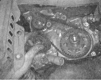
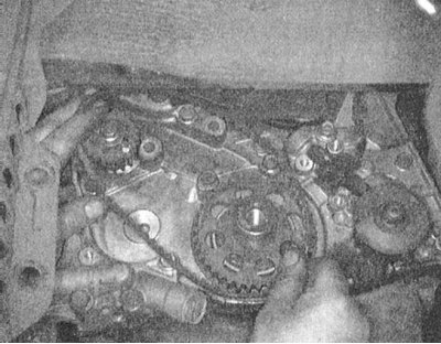
Engines 2.4 l
Removing
1. Disconnect the negative cable from the battery.
If the stereo system installed in the car is equipped with a security code, before disconnecting the battery, make sure that you have the correct combination to activate the audio system!
2. Remove the BB wires from the bracket on the top cover.
3. Empty the cooling system.
To avoid burns, proceed with the above work only after the system has completely cooled down! Do not allow antifreeze to come into contact with exposed areas of the body and painted surfaces of the car. Accidental splashes should be washed off immediately with plenty of water. Remember that antifreeze is a highly toxic liquid and getting it into the body, even in small quantities, is fraught with the most serious consequences (up to death). Never leave antifreeze stored in a loosely sealed container and clean up spilled coolant on the floor without delay. Remember that the sweet smell of antifreeze can attract the attention of children and animals. Consult any car service station about ways to dispose of used coolant. In many regions of the world, special points have been set up to receive various types of detention. Never drain old coolant down the drain and onto the ground!
4. Remove the fan assembly (ov) jacketed cooling systems (see Section Removal and installation of the engine cooling fan) and accessory drive belts.
5. If necessary, remove the radiator (see Section Removal and installation of a radiator of system of cooling (all models)).
6. Remove the powertrain upper mount assembly.
7. Remove the top section of the front timing cover.
8. Remove the steering pump, alternator, air conditioning compressor, idler pulley and related support brackets.
9. Remove the water pump and crankshaft pulleys.
10. Remove the fixing screws and remove the lower section of the timing belt cover.
11. If the belt (And) reusable, mark the direction of rotation.
12. Remove the outer gear (gas distribution) belt. Loosen the block and remove the tensioner assembly.
13. Remove the crankshaft outer gear and spacer flange.
14. Unscrew from the block and remove the tensioner of the internal toothed belt (balance shaft drive belt). Remove the inner belt.
15. To remove the camshaft sprocket, special tools such as SST MB9g67-01 and MIT308239 will be required.
Installation
1. Reinstall the camshaft gear. The required tightening torque for the central bolt is 90 Nm.
2. Achieve the alignment of the alignment marks of the gears of the balancing shaft drive belt with the reciprocal indicators on the front casing. Slide the belt over the gears so that all the slack is collected at the bottom of the belt. Once again, check the correct alignment of the labels.
3. Install the tensioner so that the axis of its roller is above and to the left of the installation bolt.
4. With your hands, move the roller up so that the long run of the belt, when pressed firmly with your thumb, sags approximately 6 mm.
5. Having blocked the roller in this position from turning, tighten the bolt with the required force (20 Nm). If the pulley shifts when released, the belt is too tight.
6. Install the timing belt tensioner, move it all the way to the water pump and temporarily tighten the bolts. Push the top end of the spring into the pump housing. Achieve the alignment of the alignment marks of the gears of the timing drive with the reciprocal pointers on the front casing.
There is a 50% chance that the balance shaft is incorrectly installed (180 degree offset) despite the correct alignment of all marks, which will lead to a noticeable increase in the level of vibrations during engine operation. In order to avoid such a situation, try to be very attentive to the implementation of the procedures listed below!
7. Before installing the timing belt, make sure the orientation of the left balance shaft is correct (oil pump gear):
- Check the correct alignment of the oil pump gear mark with the counter pointer on the front casing;
- Remove the plug from the left wall of the cylinder block in the area of \u200b\u200bthe starter mounting;
- Pass a rod with a diameter of 8 mm through the opened hole;
- With the correct alignment of the marks, the rod should enter to a depth of about 60 mm. If it is not possible to insert the rod deeper than 25 mm, the oil pump gear should be turned one full turn;
- Make sure that the labels are aligned correctly;
- Leave the rod inserted into the hole to fix the balance shaft.
8. Put the belt on the gears, first the crankshaft, then the oil pump and finally the camshaft. Make sure that all the slack is collected on the side where the idler pulley is located - the opposite run of the belt should remain taut.
9. Check the correct alignment of the alignment marks, if everything is in order, release the tensioner mounting bolt, allowing the roller to press against the belt tape and take up the slack that is taking place.
10. Remove the rod holding the balancing shaft, then rotate the crankshaft clockwise until the camshaft gear has moved two teeth, and the belt tension should automatically adjust.
Attempting to adjust the belt by hand is fraught with overtightening, which usually results in a howling sound when the engine is running!
11. Tighten the mounting bolts (first lower, then upper remote).
If, when turning the crankshaft while adjusting the belt tension, there is a feeling of resistance, the procedure should be suspended immediately, in order to avoid damage to the valves if they accidentally contact the pistons.
12. Check that the belt tension is correctly adjusted by pressing firmly with your thumb in the middle of a straight run of the belt (between the camshaft and oil pump wheels) the latter should bend about 13 mm.
13. Install the lower section of the timing drive, - make sure that all the provided gaskets are planted.
14. Install the water pump and crankshaft pulleys.
15. Install the upper section of the front timing cover.
16. Install the steering pump, alternator, air conditioner compressor, tensioner pulley, support brackets and other components removed for access.
17. Install the heat sink and cooling fan assembly with protective shroud (see Sections Removal and installation of a radiator of system of cooling (all models) and Removal and installation of the engine cooling fan).
18. Attach the spark plug wires to the support bracket on the top cover.
19. Fill the engine with fresh coolant of the required grade (see chapter Settings and ongoing maintenance).
20. Connect the negative wire to the battery.
21. Start the engine and check it for signs of leak development.
3.0L SOHC engines
Models 1992÷1994 issue
Removing
1. Installation details of the cover and timing drive components on 3.0 l models 1990÷1994. issue shown in the illustration.
2. Disconnect the negative cable from the battery.
If the stereo system installed in the car is equipped with a security code, before disconnecting the battery, make sure that you have the correct combination to activate the audio system!
3. Remove the crankcase protection elements.
4. Remove the speed control actuator (tempostat).
5. Remove accessory drive belts (see chapter Settings and ongoing maintenance).
6. Remove the air conditioning compressor drive belt tensioner assembly.
7. Remove the tensioner support bracket.
8. Support the engine with a trolley jack (in order to distribute the load, lay a block of wood between the head of the jack and the engine sump) and remove the powertrain mount bracket.
9. Disconnect the electrical wiring from the steering pump pressure switch. Remove the pump, move it aside without disconnecting the hydraulic lines, and tie it up with wire.
10. Remove the crankshaft pulley.
11. Remove the timing side cover.
12. Remove the upper and lower section of the front timing cover.
13. Mark the direction of rotation of the timing belt with chalk or paint, loosen the tensioner and remove the belt.
Try not to let coolant or engine oil get on the surface of the timing belt or timing gears!
14. Make sure that the TDC marks of the timing gears are aligned correctly.
15. Loosen the tensioner bolt and remove the timing belt. If the tensioner does not need to be removed, move it to the side as far as possible from the engine and fix it in this position by tightening the bolt.
16. If the tensioner will be removed, mark the correct mounting position of its spring - during assembly, it must be installed in the same way. Loosen the tensioner and remove it together with the spring.
Installation
1. If removed, install the tensioner, connect the upper end of the spring to the pin on the water pump housing, fix the lower end to its original position. Establish cogwheels of both camshafts, - trace alignment of adjusting marks. After turning the crankshaft, achieve alignment of the installation mark with the counter pointer on the oil pump housing.
2.Place the timing belt over the crankshaft sprocket and keeping the corresponding side taut, slip the timing belt over the front camshaft sprocket.
3. Get the belt under the drive face of the water pump, then pull it over the gear wheel of the rear camshaft and fill it under the tensioner pulley.
4. Turn the front camshaft counterclockwise, achieving belt tension in the area between the gear wheels of this and the crankshaft. If during installation of the belt misalignment of the alignment marks occurs, repeat the procedure.
5. Install the guide flange on the crankshaft gear.
6. Loosen the tensioner bolt and let the spring take up the slack in the belt.
7. Turn the crankshaft two full turns clockwise until the alignment marks are aligned again, then tighten the tensioner lock bolt to the required torque (29 Nm). Check the correct adjustment of the belt tension using a special meter. When connecting the device to the belt tape in the area in the middle between the gears of the rear camshaft and crankshaft, the reading should be (230÷310 Nm).
8. Install the timing cover, - make sure that all the seals provided for by the design are planted on the mating surfaces of the sections.
9. Install the crankshaft pulley. Screw in the fixing bolt and tighten it to the required torque (150÷160 Nm).
10. Install the motor support bracket.
11. Install the steering pump and connect the electrical wiring to the power steering pressure switch.
12. Establish an arm of a support of a suspension bracket of the power unit and keep from under the engine a jack.
13. Install the idlers and accessory drive belts.
14. Install the tempostat actuator.
15. Install the crankcase protection elements.
16. Connect the negative wire to the battery.
17. Carry out a road test of the vehicle.
Other models
Removing
1. Bring the piston of the first cylinder to the TDC position of the end of the compression stroke.
2. Disconnect the negative cable from the battery.
If the stereo system installed in the car is equipped with a security code, before disconnecting the battery, make sure that you have the correct combination to activate the audio system!
To prevent unauthorized deployment of the airbags, start the procedure at least 90 seconds after disconnecting the battery!
3. Remove the crankcase protection element.
4. Remove the pump and tempostat drive rod.
5. Remove the generator.
6. Support the engine with a trolley jack (in order to distribute the load, lay a block of wood between the head of the jack and the engine sump) and remove the powertrain mount bracket.
7. Remove the front timing covers.
8. Mark the direction of rotation of the timing belt with chalk or paint, loosen the tensioner and remove the belt.
Try not to let coolant or engine oil get on the surface of the timing belt or timing gears!
9. Make sure the engine is still at TDC and the timing marks are properly aligned.
10. Loosen the idler pulley center bolt and unbolt the auto tensioner assembly.
The auto tensioner needs to be reinstalled!
11. Remove the timing belt.
12. Having blocked the camshaft from turning with a wrench, remove the gear wheel from it.
13. Clamp the auto-tensioner assembly in a soft-jawed vise.
There is a protruding plug on the back side of the tensioner assembly - in order to avoid accidental damage, place a washer of the appropriate thickness under the vise jaws.
14. Slowly push the tensioner rod in until the mounting holes line up.
15. Thread a 1.4 mm wire through the aligned holes, release the tensioner assembly from the vise and install it on the engine. Screw in the mounting bolts and tighten them with the required force (24 Nm).
before installing the mating surface of the tensioner, it should be carefully cleaned, the threaded part of the old bolts should be lubricated with sealant. When replacing bolts, sealant is applied only to those whose caps are not marked with white paint.
Installation
1. If removed, install the tensioner. Connect the upper end of the spring to the pin on the water pump housing, fasten the lower end to the tensioner assembly, bringing it strictly to the previous installation position.
2. Make sure that the alignment marks of both camshafts are aligned correctly.
3. Turn the crankshaft so that its alignment mark is aligned with the counter pointer on the front cover.
4. Place the timing belt on the crankshaft sprocket, then, while holding the corresponding side of it taut, insert the timing belt on the front sprocket (left) camshaft.
5. Thread the belt under the water pump drive roller, then pull it over the gear wheel of the rear (right) camshaft. Finally, tuck the belt under the tension pulley.
6. Loosen the adjuster locking bolt and lightly press the tensioner against the belt webbing. Make sure that all alignment marks are correctly aligned.
7. Rotate the crankshaft two full turns clockwise, finally aligning the marks again.
8. Tighten the tensioner lock bolt to specification (26 Nm).
9. Install the timing cover sections and all other components removed for access.
10. Connect the negative cable to the battery.
11. Carry out a road test of the vehicle.
3.0L DOHC engines
Models 1992÷1994 issue
Removing
1. Bring the engine to the TDC position of the end of the compression stroke of the piston of the first cylinder.
2. Disconnect the negative cable from the battery.
If your vehicle's stereo system is equipped with a security code, make sure you have the correct combination to put the audio system into operation before disconnecting the battery!
3. Remove the crankcase protection elements.
4. Remove the speed control actuator (tempostat).
5. Remove the generator.
6. Remove the air hose and tube.
7. Remove the tensioner assembly and steering pump drive belt.
8. Remove the crankshaft pulley.
9. Disconnect the wiring from the brake fluid level sensor.
10. Remove the upper section of the timing cover.
11. Support the engine with a trolley jack (in order to distribute the load, lay a block of wood between the head of the jack and the engine sump) and remove the powertrain mount bracket.
12. Remove an intermediate roller of a belt of a drive of the generator/compressor K/V.
13. Remove the motor support bracket.
Mounting bolts have different lengths and must be installed strictly in their original places during assembly.
14. Remove the lower section of the front timing cover - try to remember the mounting position of the mounting bolts.
15. Mark the direction of rotation of the timing belt with chalk or paint, loosen the tensioner and remove the belt.
Try not to let coolant or engine oil get on the surface of the timing belt or timing gears! Make sure the engine is still at TDC.
16. Loosen the tensioner bolt and remove the belt.
17. Remove tensioner assembly.
Installation
1. If the auto tensioner rod is fully extended, reinstall it:
- Place the tensioner assembly in a soft-jawed vise;
- Slowly squeezing the vise jaws, sink the rod to align its hole with the hole in the cylinder;
- Having threaded a piece of hard wire into the aligned holes, fix the stem in a recessed position;
- Remove the assembly from the vise.
2. Without removing the wire, install the tensioner on the engine.
3. If the correct alignment of the installation marks was violated, perform the manipulations described below.
- Try not to stick your fingers between the spokes of the gears, as the latter may suddenly turn under the influence of the force developed by the valve springs!
- Get the timing mark on the crankshaft gear to the correct position, then turn the wheel 2 teeth clockwise to eliminate the risk of piston contact with the valve when turning the camshafts;
- Alternately achieve the correct location of the alignment marks of the gears of each of the camshafts.
- With the simultaneous opening of the intake and exhaust valves of one cylinder, they can cling to each other, therefore, in the event of the slightest resistance, the position of the second camshaft should be immediately corrected;
- Align the timing marks on the crankshaft again, then turn the latter one more tooth counterclockwise, thereby preparing the wheels for installing the timing belt.
4. Install the timing belt in the following order (immediately fix the belt on the gears of the camshafts with spring clips):
- 1 - gear wheel of the final camshaft of the front cylinder head;
- 2 - gear wheel of the intake camshaft of the front cylinder head;
- 3 - drive roller of the water pump;
- 4 - gear wheel of the intake camshaft of the rear cylinder head;
- 5 - gear wheel of the final camshaft of the rear cylinder head;
- 6 - intermediate roller;
- 7 - gear wheel of the crankshaft;
- 8 - tensioner roller.
5. Turn the tensioner pulley so that the holes in its pin are directly above the center bolt, then press the tensioner pulley against the belt tape and at the same time tighten the center bolt.
6. Make sure that the alignment marks are correctly aligned and remove the belt clips.
7. Turn the crankshaft 1/4 turn counterclockwise, then return it back, once again achieving the correct alignment of the marks.
8. Loosen the central bolt of the tension roller. Using special tool type MD998767 and a torque wrench, apply a torque of 10 Nm to the roller and retighten the bolt (make sure that the tensioner does not rotate when tightening the bolt).
9. Remove the wire fixing the auto-tensioner rod.
10. Rotate the crankshaft two full turns clockwise and allow the components to seat for at least 5 minutes. Check the freedom of movement of the adjusting pin in the tensioner hole.
11. Measure the protrusion of the auto tensioner (distance between tensioner arm and its housing). The required value is 3.8÷4.5 mm. If the measurement result is out of range, repeat the adjustment procedure.
12. Install the lower section of the front timing belt cover on the engine - make sure that all the seals provided for by the design are installed.
13. Install the engine support bracket, - make sure that all bolts are installed strictly in their original places, - pre-lubricate the working surface of the countersunk bolt, tighten the bolt slowly.
14. Install the intermediate roller.
15. Establish an arm of a support of a suspension bracket of the power unit, lower a jack and take it from under the engine.
16. Reinstall the upper section of the front timing belt cover - make sure that all the seals provided for by the design are installed.
17. Connect electroconducting to the gauge of level of a brake liquid.
18. Install the crankshaft pulley. Screw in the fixing bolt and tighten it to the required torque (180÷190 Nm).
19. Install the tensioner assembly and steering pump drive belt.
20. Install the air hose and tube.
21. Install the generator.
22. Install the tempostat actuator.
23. Install the crankcase protection elements.
24. Connect the negative wire to the battery.
25. Carry out a road test of the vehicle.
Models 1995 and 1996 issue
Removing
1. Bring the engine to the TDC position of the end of the compression stroke of the piston of the first cylinder.
2. Disconnect the negative cable from the battery.
If your vehicle's stereo system is equipped with a security code, make sure you have the correct combination to put the audio system into operation before disconnecting the battery!
To avoid unauthorized deployment of airbags, start the procedure at least 90 seconds after disconnecting the battery!
3. Remove the crankcase protection elements.
4. Remove the speed control actuator (tempostat).
5. Remove the generator.
6. Remove the air hose and tube.
7. Remove the tensioner assembly and steering pump drive belt.
8. Remove the crankshaft pulley.
9. Disconnect the wiring from the brake fluid level sensor.
10. Remove the upper section of the timing cover.
11. Support the engine with a trolley jack (in order to distribute the load, lay a block of wood between the head of the jack and the engine sump) and remove the powertrain mount bracket.
12. Remove an intermediate roller of a belt of a drive of the generator/compressor K/V.
13. Remove the engine support bracket.
Mounting bolts have different lengths and must be installed strictly in their original places during assembly.
14. Remove the lower section of the front timing cover - try to remember the mounting position of the mounting bolts.
15. Mark the direction of rotation of the timing belt with chalk or paint, loosen the tensioner and remove the belt.
Try not to let coolant or engine oil get on the surface of the timing belt or timing gears! Make sure the engine is still at TDC.
16. Loosen the tension roller bolt and remove the belt.
To avoid damage to the valves when they hit the piston bottoms, do not allow the camshaft gears to turn with the timing belt removed!
17. Turn out fixing bolts and remove assembly of an automatic natyazhitel.
Installation
1. Cock the auto tensioner:
- Place the tensioner assembly in a soft-jawed vise;
- Slowly squeezing the vise jaws, sink the rod to align its hole with the hole in the cylinder;
- Having threaded a piece of hard wire with a diameter of 1.4 mm into the aligned holes, fix the stem in a recessed position;
- Remove the assembly from the vise.
2. Without removing the wire, install the tensioner on the engine. Screw in the mounting bolts and tighten them to the required torque (24 Nm).
3. Achieve the correct location of the installation mark of the crankshaft gear, then turn the wheel 1 tooth counterclockwise.
4. Achieve the alignment of the alignment marks of the camshafts.
5. Install the timing belt in the following order (immediately fix the belt on the gear wheels with spring clips):
- 2 - gear wheel of the intake camshaft of the front cylinder head;
- 3 - drive roller of the water pump;
- 4 - gear wheel of the intake camshaft of the rear cylinder head;
- 5 - gear wheel of the exhaust camshaft of the rear cylinder head;
- 6 - tensioner roller;
- 7 - gear wheel of the crankshaft;
- 8 - intermediate roller.
6. Make sure that the crankshaft marks are aligned correctly, then press the tensioner pulley against the belt tape. Once the belt slack is taken up, tighten the tensioner bolt.
7. Turn the tensioner roller so that the holes in its pin are directly above the central bolt.
8. Make sure that the alignment marks are correctly aligned and remove the clips fixing the belt.
9. Turn the crankshaft 1/4 turn counterclockwise, then return it back, once again achieving the correct alignment of the marks.
10. Loosen the central bolt of the tension roller. Using special tool type MD998767 and a torque wrench, apply a torque of 10 Nm to the roller and tighten the bolt again, this time with the required torque (49 Nm) (make sure that the tensioner does not rotate when tightening the bolt).
11. Rotate the crankshaft two full turns clockwise and allow the components to seat for at least 5 minutes. Check the freedom of movement of the adjusting pin in the auto-tensioner hole.
12. Remove the wire fixing the tensioner rod.
13. Measure the protrusion of the auto tensioner (distance between tensioner arm and its housing). The required value is 3.8÷4.5 mm. If the measurement result is out of range, repeat the adjustment procedure.
14. Install the lower section of the front timing belt cover on the engine - make sure that all the seals provided for by the design are installed.
15. Install the engine support bracket, - make sure that all bolts are installed strictly in their original places, - pre-lubricate the working surface of the countersunk bolt, tighten the bolt slowly.
16. Install the intermediate roller.
17. Establish an arm of a support of a suspension bracket of the power unit, lower a jack and take it from under the engine.
18. Reinstall the upper section of the front timing drive cover - make sure that all the seals provided for by the design are installed.
19. Connect electroconducting to the gauge of level of a brake liquid.
20. Install the crankshaft pulley. Screw in the fixing bolt and tighten it to the required torque (180÷190 Nm).
21. Install the tensioner assembly and steering pump drive belt.
22. Install the air hose and tube.
23. Install the generator.
24. Install the tempostat actuator.
25. Install the crankcase protection elements.
26. Connect the negative wire to the battery.
27. Carry out a road test of the car.
Engines 3.5 l
Removing
1. Disconnect the negative cable from the battery.
If the stereo system installed in the car is equipped with a security code, before disconnecting the battery, make sure that you have the correct combination to activate the audio system!
2. Empty the cooling system.
To avoid burns, proceed with the above work only after the system has completely cooled down! Do not allow antifreeze to come into contact with exposed areas of the body and painted surfaces of the car. Accidental splashes should be washed off immediately with plenty of water. Remember that antifreeze is a highly toxic liquid and getting it into the body, even in small quantities, is fraught with the most serious consequences (up to death). Never leave antifreeze stored in a loosely sealed container and clean up spilled coolant on the floor without delay. Remember that the sweet smell of antifreeze can attract the attention of children and animals. Consult any car service station about ways to dispose of used coolant. In many regions of the world, special points have been set up to receive various types of detention. Never drain old coolant down the drain and onto the ground!
3. Remove the accessory drive belts.
4. Remove the top radiator shroud.
5. Remove the fan drive pulley assembly.
6. Unbolt the steering pump from its support bracket without disconnecting the hydraulic hoses, move the pump to the side and secure it with wire. Remove the pump support bracket.
7. Remove the cooling fan support bracket.
8. On some models, the crankshaft pulley must be removed to gain access to the bolts securing the lower section of the front timing cover.
9. Remove the mounting bolts and remove the upper and lower timing covers.
10. Disconnect the wiring from the crankshaft position sensor (CKP).
11. Using special tools MB9g67-01 and MD998754, remove the pulley from the crankshaft journal.
12. Thoroughly wipe the timing marks on the timing gears with a clean rag. And make sure they are aligned correctly.
13. Mark the direction of rotation of the timing belt with chalk or paint, loosen the tensioner and remove the belt.
Try not to let coolant or engine oil get on the surface of the timing belt or timing gears! Make sure the labels are aligned correctly.
14. Loosen the central bolt of the tension roller and remove the timing belt.
15. Remove the auto tensioner assembly, idler pulley and tensioner arm.
16. Keeping the camshafts from turning with a suitable key, give the fixing bolts and remove the corresponding gear wheels.
Installation
1. Replace the crankshaft pulley and rotate the crankshaft gear of the latter three teeth clockwise, thereby bringing the engine to a position slightly beyond TDC of the end of the compression stroke of the piston of the first cylinder.
2. If removed, reinstall the camshaft gears. Tighten the fixing bolts to the required torque (88 Nm).
3. Achieve the alignment of the alignment marks of the gears of the camshafts of the left and right cylinder heads. Use a wrench to block the gears from turning.
4. Put the belt on the gears of the camshafts of the right cylinder head and fix it with a pair of clerical clips.
5. Get the timing belt under the water pump drive roller.
6. Make sure that the marks of the gear wheels of the camshafts of the left cylinder head are aligned correctly, put a belt on the wheels and fix it with a pair of spring stationery clips.
7. Get a belt under an intermediate roller.
8. Turn the crankshaft one full turn counterclockwise and again achieve alignment of the alignment marks.
9. Get a belt under a tension roller.
10. Turn the roller with the pin hole up, press it against the belt tape and tighten the locking bolt with a force of 48 Nm.
11. Slowly turn the crankshaft two full turns clockwise until the alignment marks are aligned. Remove the four clips securing the belt to the camshaft gears.
12. Replace the timing cover.
13. Install the crankshaft pulley. Screw in the fixing bolt and tighten it to the required torque (150 Nm).
14. Install on the engine all the components that were removed for the purpose of securing - proceed in the reverse order of their dismantling.
15. Fill the cooling system with fresh mixture of the required grade (see chapter Settings and ongoing maintenance).
16. Connect the negative wire to the battery.
17. Start the engine and check it for signs of leak development.