
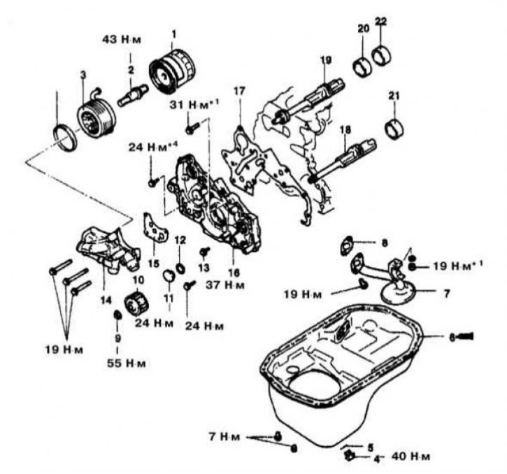
Details of installation of balancing shafts on engines 2.0 l and 2.4 l
1 - Oil filter; 2 - Oil cooler bolt *3; 3 - Oil cooler *3; 4 - Drain plug; 5 - Sealing washer; 6 - Oil pan; 7 - Oil intake; 8 - Sealing gasket; 9 - Flange nut; 10 - Oil pump gear *2; 11 - Cork; 12 - O-ring; 13 - Flange bolt; 14 - Oil filter support bracket; 15 - Sealing gasket of the support bracket; 16 - Front cover; 17 - Sealing gasket; 18 - Left balancing shaft *2; 19 - Right balancing shaft *; 20 - Front bearing of the balancing shaft *2; 21 - Rear bearing of the left balancing shaft; 22 - Rear bearing of the right balancing shaft *2
Notes:
*1 DOHC
*2 Engines with balance shafts
*3 Dali turbocharged
*4 Engines without balance shafts
*5 Engines with air-type oil cooler
Engines 2.0L and 2.4L
To perform this procedure, you will need a special mandrel for the oil seal MD998285, as well as a tool MD998162 to remove the plug from the engine front cover.
Removing
1. Details of the installation of balancing shafts on 2.0 l and 2.4 l engines are shown in the illustration.
2. Disconnect the negative cable from the battery.
If the stereo system installed in the car is equipped with a security code, before disconnecting the battery, make sure that you have the correct combination to activate the audio system!
3. Jack up the car and put it on stands.
4. Drain the engine oil.
5. Remove the oil filter, oil pressure switch, oil gauge sensor, support bracket and oil filter seal.
6. Remove the oil pan, oil pickup and sealing gasket.
7. Unscrew the plug and remove the components of the oil pump pressure reducing valve (don't forget to remove the sealing washer).
8. Lower the vehicle to the ground.
9. Hang the engine on the winch.
10. Remove the powertrain front mount bracket and accessory drive belt.
11. Remove timing belts and timing/balance shaft wheels.
12. Using the special tool MD998162, remove the plug from the engine front cover.
13. Remove the plug from the side wall of the block and, having inserted a Phillips screwdriver with a sting with a diameter of 8 mm, through the opened hole, block the balancing shaft with it.
14. Turn out a bolt of fastening to a balancing shaft of a conducted gear wheel of the oil pump.
15. Unscrew and mark the bolts of the front cover - the bolts have different lengths and during installation must be screwed strictly into their original places.
16. Remove the front cover of the oil pump housing.
If necessary, the balancing shaft can be removed complete with cover.
17. Remove the balancing and crankshaft seals and the front cover seal.
18. Remove the balancing shafts and evaluate their wear. Check the patency of the oil flow of the shaft, check the condition of the bearing journals. Measure the operating clearances in the bearings and compare the measurement results with the requirements of the Specifications (right shaft front bearing: 0.03÷0.06 mm, right shaft rear bearing: 0.02÷0.05 mm; front left shaft bearing: 0.05÷0.09 mm, left shaft rear bearing: 0.04÷0.08 mm). If necessary, replace the relevant bearings, shaft or front cover.
Installation
1. Lubricate the surfaces of the bearings and bearing journals of the shafts with clean engine oil. Carefully thread the balance shafts into the engine block.
2. Thoroughly clean the mating surfaces of the block and the front cover of the engine, finally wiping them with a rag soaked in acetone. Install a new seal.
3. Having followed the correct alignment of the alignment marks, plant the drive and driven gears in the assembly of the front casing of the oil pump.
4. Lubricate the gears with engine oil. After replacing the gasket, install the oil pump cover. screw in the mounting bolts and tighten them with the required force (18 Nm).
5. Using as a mandrel an end head of the appropriate size, or a piece of pipe of a suitable diameter, plant the front crankshaft oil seal in its nest in the front engine casing.
6. Having again selected a suitable mandrel, press the balancing shaft oil seal into the front casing.
7. Attach tool MD998285 to the crankshaft trunnion. Lubricate the outer edge of the guide tool with clean engine oil.
8. Install the front cover on the engine. Install and temporarily tighten the flange bolts.
9. After replacing the gasket, install the oil filter support bracket. Screw in the four fixing bolts and tighten them to the required torque (22 Nm).
10. Insert an 8mm Phillips screwdriver bit into the side hole in the block.
11. Fix the driven gear of the oil pump on the left balancing shaft, - tighten the flange bolt with a force of 40 Nm.
12. Fit a new O-ring into the groove in the front casing. Using a special drive head, install the plug and tighten it with a force of 27 Nm.
13. Insert the relief valve components into their seat in the oil filter support bracket (plunger and spring), tighten to the required torque (50 Nm) plug.
Don't forget to replace the seal.
14. Thoroughly clean the mating surfaces of the oil pan and engine block.
15. Lay a pad of sealant about 4 mm wide into the groove on the sump flange (sealant is applied to the inside of the bolt holes).
16. No later than 15 minutes after applying the sealant, press the tray against the block and install the holders. Screw in the mounting bolts and tighten them with the required force (8 Nm).
17. Install the gauge assembly and the engine oil pressure sensor. Restore the original wiring connection.
18. Install a new oil filter and fill the engine with fresh engine oil of the appropriate grade (see chapter Settings and ongoing maintenance).
19. Install toothed belts and other components of the timing drive and balancing shafts. Make sure the alignment marks are correctly aligned (see Section Removing and installing timing cover and timing belt).
20. Install other components removed for access.
21. Connect the negative cable to the battery. Start the engine and check it for signs of leaks.
22. Check up correctness of installation of an advancing angle of ignition. Make appropriate adjustments if necessary.