
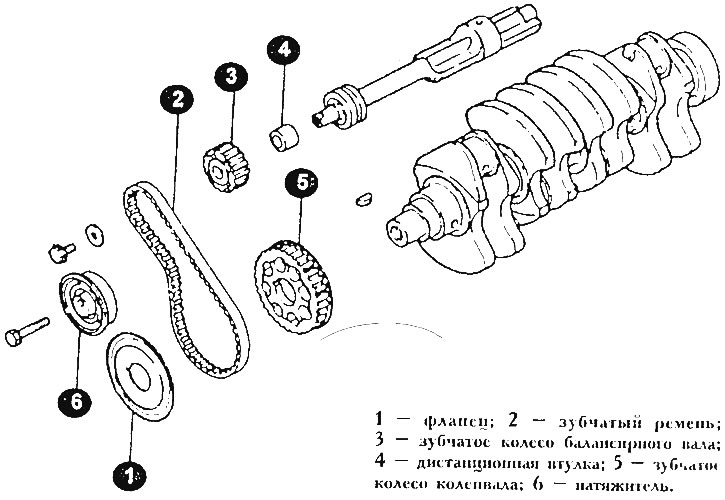
balance shaft drive
1 - flange; 2 - toothed belt; 3 - gear wheel balancer shaft; 4 - remote bushing; 5 - crankshaft gear; 6 - tensioner.
Timing mechanism parts can be replaced without removing the engine from the vehicle. The procedure for removing these parts is described in the section that describes how to disassemble the engine.
The description of the following adjustment procedure is carried out on the assumption that all parts of the gas distribution mechanism are removed (e.g. for overhaul or replacement of parts).
Install the balance shaft gear wheel, screw the wheel bolt.
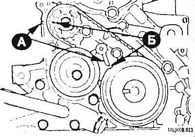
Put the drive wheel on the toe of the crankshaft. Align match marks (A) And (B) on each wheel.
Put the belt on both sprockets so that the side of the belt against which the tensioner rests is taut.
Install tensioner. The center of the tensioner roller should be located to the left of the tensioner bolt. The collar on the roller flange must face outwards (from the engine). The figure shows the tensioner pulley after installation on the engine.
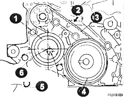
1 - tensioner; 2 - belt tension side; 3 - toothed belt; 4 - flange flange; 5 - fastening bolt; 6 - the center of the tensioner roller.
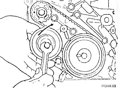
Feed the tensioner in the direction of the arrow while lifting with your finger to give the required tension to the belt. In this position, fix the tensioner by tightening the bolt. When tightening the bolt, keep the shaft from turning.
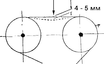
Make sure that the alignment marks on the wheels and the front cover are not broken. Check the tension of the belt by pressing with your index finger in the place indicated in the figure. The deflection of the belt should be 5-7 mm.
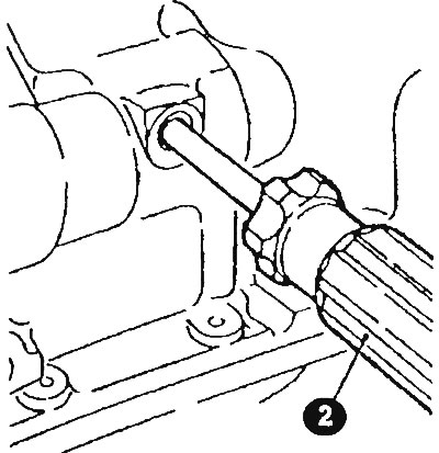
Install the oil pump wheel and tighten the bolt to 50-60 Nm. Check the correct installation of the balance shaft with a screwdriver (2) with a blade with a diameter of 8 mm, inserted into the hole in the left side of the cylinder block. If the screwdriver goes 60 mm, then the shaft is set correctly, if the screwdriver blade goes 25 mm, then turn the oil pump wheel 1 turn and check the alignment of the alignment marks again. Remove the screwdriver only after installing the belt.
Installing the camshaft belt
Insert the tensioner into the lowest position on the slots in the fuel pump bracket.
Remove glow plugs.
Loosen the lock nuts of the adjusting screws and unscrew all the screws so that their ends protrude 2 mm.
Turn the crankshaft so that the piston of the 1st cylinder is set to the TDC of the compression stroke, check the alignment of the marks.
Put on the belt, turning on each wheel in turn. When putting on the belt, take up the slack between all the wheels and also between the pulley and adjacent wheels.
First, the belt is put on the crankshaft wheel, then on the tensioner roller, on the camshaft wheel, then on the fuel injection pump wheel, and finally on the oil pump wheel. Rotate the crankshaft half a tooth of the camshaft wheel in the opposite direction to the normal movement of the belt. In this case, the slack of the belt along its entire length will be selected. Finally put the belt on the tensioner.
Remove the screwdriver that was inserted into the cylinder block. Loosen the tensioner mounting bolt 1/4 turn, while the tensioner pulley will rest against the belt.
Turn the crankshaft counterclockwise by 3 teeth of the camshaft wheel, starting from the alignment mark, fix the wheel in this position. Make sure that all the teeth of the gears are in the grooves of the belt. Turn the crankshaft in a clockwise direction until the marks on the camshaft wheel and on the front cover are aligned.
Check the tension of the belt by the amount of deflection when pressing with the index finger in the place indicated in the figure. If the deflection is out of specification, repeat the tension adjustment.
Make sure that the alignment of all marks is not broken, turn the crankshaft in the direction of normal rotation and check the alignment of the marks again. It is not allowed to turn the crankshaft in the opposite direction.
Install the removed parts in reverse order.