



Contents: Removal ⤓ Removal the drive shaft mounting nut ⤓ Removal the self-locking nut (tie…⤓ Removal the drive shaft ⤓ Removal the Inner Drive Shaft (4WD…⤓ Installing the drive shaft ⤓ Installing the cushion and…⤓ Installing the drive shaft mounting…⤓
Caution! When removing and installing the drive shaft, be careful not to hit the toothed ring of the wheel speed sensor, which is installed on the outer ring of the outer constant velocity joint. Otherwise, the toothed ring of the sensor will be damaged.
When performing maintenance work, be careful not to hit the pole piece located at the top of the front wheel speed sensor.
Removal
Drain the transmission oil. (4WD models) Drain the transfer case oil.
Remove the exhaust pipe.
Attention! To avoid damage, when loosening the drive shaft mounting nut, hang the wheel to relieve the hub bearing.
Removal the drive shaft mounting nut
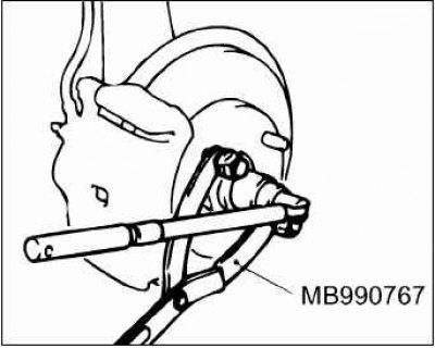
To secure the hub and unscrew the drive shaft mounting nut, use a special holder (MB990767).
Caution! Do not remove the nut from the ball joint pin. Only loosen it. Use a special tool to avoid damaging the threads on the ball joint pin. Tie the puller with a cord to prevent it from falling.
Removal the self-locking nut (tie rod end fastening)
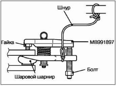
Install the ball joint puller (MB991897) as shown in the figure.
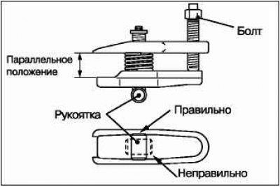
If necessary, turn the handle and bolt to set the legs parallel to each other. Tighten the bolt by hand, keeping the legs parallel.
Attention! After setting the paws parallel to each other, make sure that the handle is in the position shown in the figure.
Tighten the bolt with a wrench to disconnect the tie rod end.
Removal the drive shaft
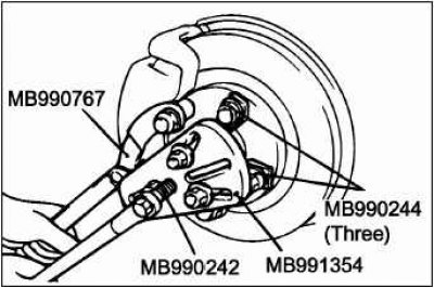
To remove the drive shaft from the hub, use the following special tool.
- Drive shaft puller (MB990241).
- Puller screw (MB990242).
- Puller bracket (MV990244).
- Puller base (MV991354).
- Holder (MB990767).
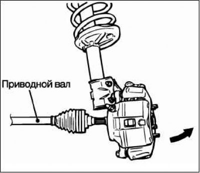
Remove the drive shaft from the hub by grasping the bottom of the brake disc and pulling it towards you.
Caution! Do not apply force to the drive shaft. Otherwise, you may damage the constant velocity joint. Use a pry bar for this.
Caution: When removing the drive shaft from the gearbox, be careful not to damage the oil seal with the drive shaft splines.
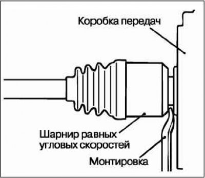
Insert a pry bar between the transmission housing and the drive shaft. Use the pry bar as a lever and pull the drive shaft out of the transmission.
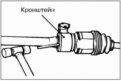
If the inner shaft is difficult to remove from the gearbox, remove the shaft by lightly tapping the intermediate support bracket assembly with a plastic hammer.
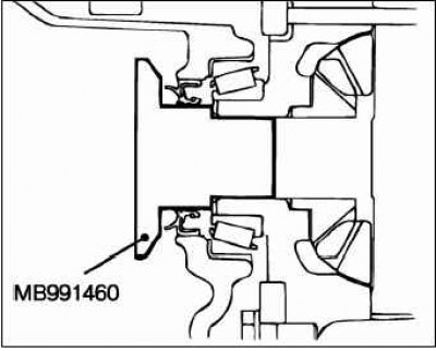
Install a special plug (MB991460) to prevent foreign materials from entering the gearbox housing.
To avoid damage when removing the drive shaft, the wheel should be jacked up to relieve the hub bearing. If it is necessary to move the vehicle with support on the wheels, temporarily secure the bearing using the following special tool.
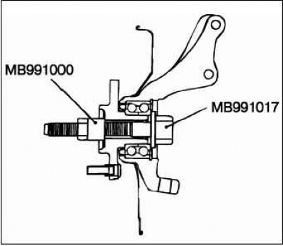
- Expansion sleeve (MB991000).
- Device for dismantling and installing the front wheel hub (MB991017).
Removal the Inner Drive Shaft (4WD Models)
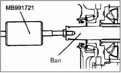
Using a special tool, remove the shaft.
Caution: Do not damage the seal with the splines of the wheel drive shaft when removing the shaft.
Installing the drive shaft
Caution: When installing the drive shaft, be careful not to damage the oil seal with the drive shaft splines.
Installing the cushion and self-locking nut (anti-roll bar fastening)
Install the cushion and bushing as shown in the figure. Tighten the self-locking nut so that the protruding length (A) of the stabilizer bar mounting bolt corresponds to the required value.
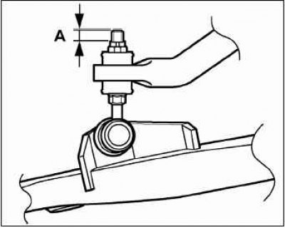
Required value (A): 9.4 ±0.3 mm.
Note: Be careful to maintain the correct orientation of the drive shaft washer and nut.
Caution! Before final tightening of the drive shaft mounting nuts, make sure that the hub bearings are not under load. Otherwise, the bearing will be damaged.
Installing the drive shaft mounting washer and nut
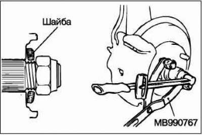
Using the special holder (MB990767), tighten the drive shaft mounting nut to the specified torque.
Tightening torque value: 245±29 Nm.