Contents: Removal the retaining ring ⤓ Removal the universal joint cross…⤓ Removal the intermediate support fork ⤓ Removal the CV joint assembly ⤓ Removal the protective cover of the…⤓ Installing a protective cover for…⤓ Installing the CV joint assembly ⤓ Installing the CV joint protective…⤓ Installation of intermediate support…⤓ Installing the intermediate support…⤓ Installing the crosspiece and bearing ⤓ Installing the retaining ring ⤓
Removal the retaining ring
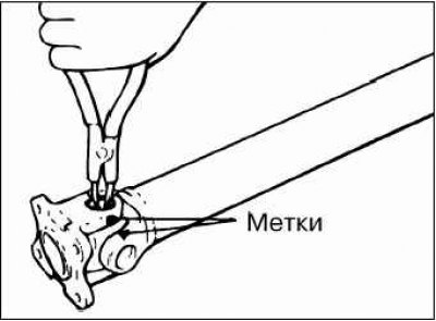
Before removing the retaining ring, mark the position of the universal joint forks.
Removal the universal joint cross bearing
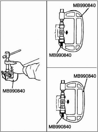
Using a special tool, press out the crosspiece bearing from one side of the universal joint while pressing on the bearing from the other side of the crosspiece.
Move the special tool to the other side and press out the second bearing by pressing on the crosspiece.
Caution! Do not knock out the bearings when removing them, as this may lead to imbalance of the driveshaft.
Removal the intermediate support fork
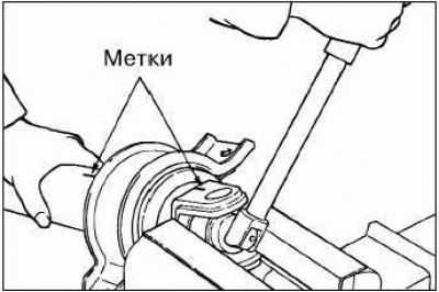
Before removing the intermediate shaft support fork, apply alignment marks to the relative positions of the fork and the intermediate propeller shaft.
Removal the intermediate support assembly
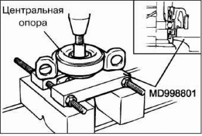
Mark the relative positions of the intermediate propeller shaft, CV joint assembly and flange, then remove the bolt.
Using a puller, remove the intermediate support assembly from the intermediate propeller shaft.
Caution: Using too much grease will result in assembly difficulties and incorrect snap ring selection
Removal the CV joint assembly
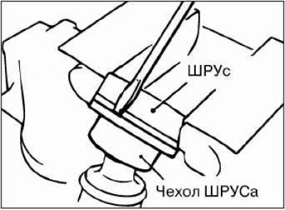
Remove the protective cover from the CV joint assembly.
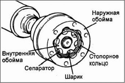
Mark the relative positions of the outer race, separator and inner race of the CV joint, then remove the retaining ring, outer race and balls.
Note: Remember or write down the location of the balls so as not to confuse their original location during installation.
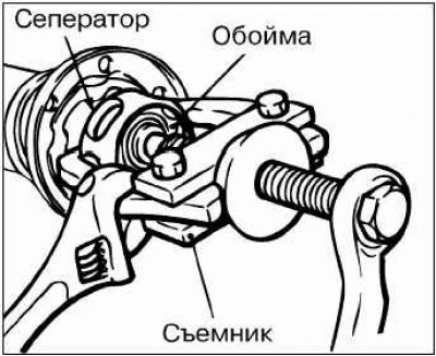
Using a universal puller, remove the inner race and CV joint separator from the intermediate propeller shaft.
Remove old grease and clean the outer and inner races, separator and CV joint balls.
Removal the protective cover of the CV joint
If you plan to reinstall the CV joint protective boot, wrap the splines of the rear propeller shaft with insulating tape before removing it.
Installing a protective cover for the CV joint
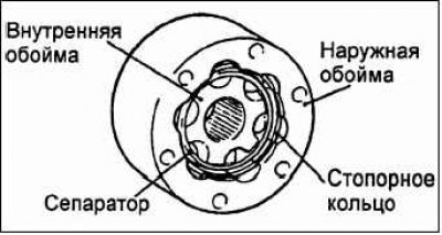
Install the CV joint protective boot clamp.
Wrap the splines of the intermediate driveshaft with insulating tape, then install the CV joint protective boot.
Installing the CV joint assembly
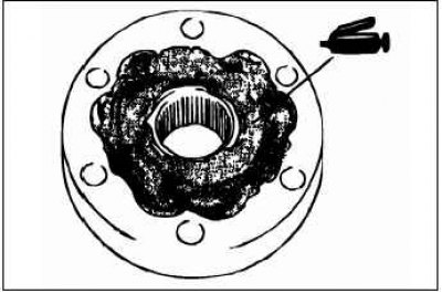
Apply a thin layer of special consistent grease to the grooves under the balls on the outer and inner CV joint races.
Install the outer race, separator, balls and inner race, aligning the relative position marks.
Install the retaining ring.
Apply special consistent grease to the CV joint assembly.
Quantity: 90–100 g.
Apply a small amount of special glue to three points on the surface of the ball grooves (shown by arrows in the figure), located at equal distances from each other around the circumference of the CV joint, in which there are grooves for the rubber seal, and then install the rubber seal on the CV joint.
Adhesive: 3M Stud Locking #4170 or equivalent.
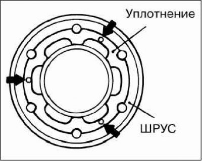
Position the CV joint so that the side with the grooves on which the rubber CV joint seal was previously installed is facing the CV joint protective boot.
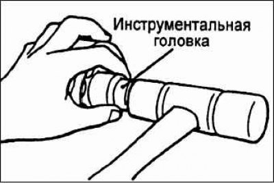
Align the marks on the CV joint assembly and the intermediate drive shaft, then use a tool head to install the CV joint assembly onto the intermediate drive shaft.
Align the bolt holes on the CV joint boot and the CV joint assembly using the mounting bolts, and install the boot on the CV joint.
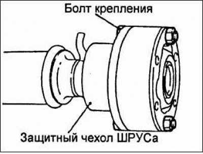
Install the rubber seal on the CV joint from the flange side.
Installing the CV joint protective boot clamp
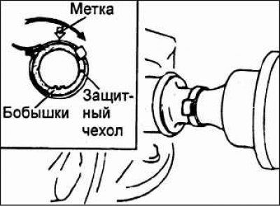
Position the boot clamp lock so that it is on the opposite side of the boot from the boot vent bosses (arrow in the illustration). Make sure there is no grease around the boot vent bosses, as grease will impede ventilation through the channels.
Installation of intermediate support assembly, flange and self-locking nut
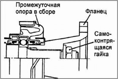
Install the intermediate support assembly onto the intermediate propeller shaft as shown in the figure.
Align the previously made relative position marks on the flange and intermediate propeller shaft.
Press the flange and intermediate support assembly firmly together, tightening the self-locking nut.
Installing the intermediate support assembly, intermediate support fork and self-locking nut
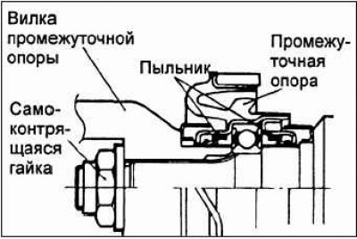
Install the intermediate support assembly onto the intermediate propeller shaft as shown in the figure.
Align the marks relative to the position of the intermediate support fork and the intermediate propeller shaft.
Press the fork and intermediate support assembly firmly together, tightening the self-locking nut.
Installing the crosspiece and bearing
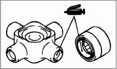
Apply grease to the bearing cross and working surfaces.
Caution: Using too much grease will result in assembly difficulties and incorrect snap ring fit.
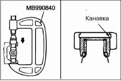
Using a special tool, press the crosspiece bearing into the fork so that the groove for the retaining ring is completely visible. Caution: Be careful when pressing the crosspiece bearings, as tilting the bearing during pressing will cause it to be damaged by the crosspiece.
Using a special tool, press the bearing on the opposite side of the crosspiece into the fork.
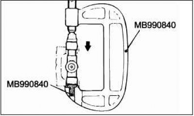
Align the relative position marks of the fork and the cardan shaft, install the second pair of universal joint cross bearings in accordance with the procedures given in subparagraphs "a" and "b".
Installing the retaining ring
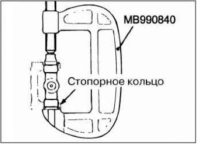
Install the snap ring on one side of the universal joint cross.
Place the puller on the side opposite to where the retaining ring is installed and press the bearing until it touches the retaining ring.
Install the snap ring on the opposite side. Measure the axial clearance of the universal joint cross bearing (between the snap ring and the bearing) using a flat feeler gauge.
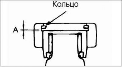
Nominal clearance: 0.02–0.06 mm.
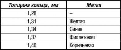
Caution! The retaining rings on both sides must be of the same thickness.
If the axial clearance exceeds the nominal value, adjust it by selecting a retaining ring of suitable thickness.