
Removing
Note:
- − Removal of parts is carried out in the order of numbers indicated in the figure "Removing the cardan shaft".
- − When removing parts, pay attention to the following operations
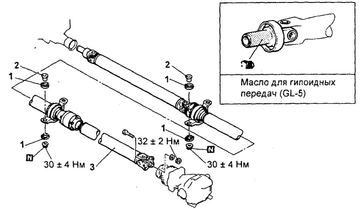
Removing the cardan shaft. 1 - vibration isolator, 2 - bushing, 3 - cardan shaft assembly.
Removing the cardan shaft.
A) Mark the driveshaft flange and gearbox flange.
b) Remove the cardan shaft.
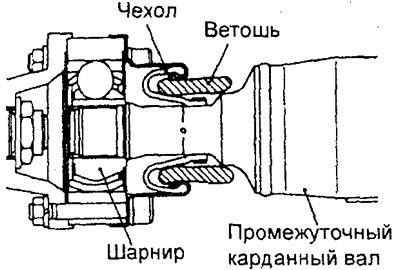
Attention: remove the cardan shaft in a straight and horizontal plane so as not to damage the protective cover.
Note: put a rag in the constriction of the protective cover.
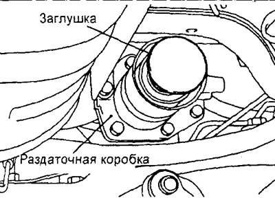
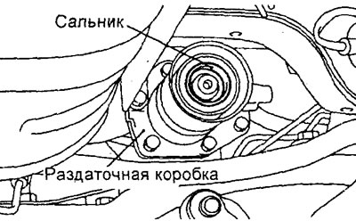
V) Install a plug to keep dirt out of the transfer case.
Examination
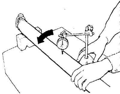
Check driveshaft runout.
Maximum runout - 0.5 mm
Installation
Note: Installation is in the reverse order of removal. Pay attention to the following operations when installing parts.
1. Installing the cardan shaft.
Attention: Be careful not to damage the transfer case seal.
Align the marks on the driveshaft flange and gearbox flange.
Attention: Before tightening nuts and bolts, carefully clean the threads of the fasteners from oil or grease.
Disassembly
Note:
- - Disassembly of the cardan shaft is carried out in the order of the numbers indicated in the figure "Dismantling the cardan shaft".
- - When disassembling, pay attention to the following operations.
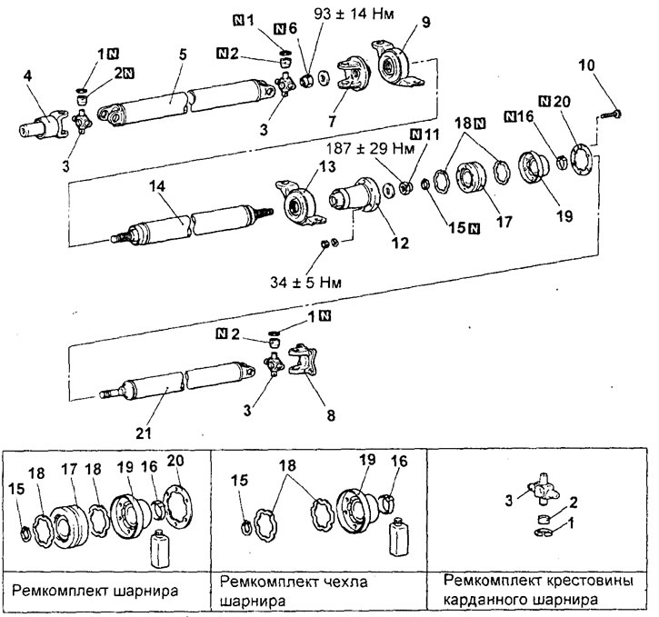
Disassembly of the cardan shaft. 1, 15 - retaining ring, 2 - universal joint bearing, 3 - universal joint cross, 4 - sliding yoke, 5 - front propeller shaft, 6, 11 - self-locking nut, 7 - intermediate cardan shaft yoke, 8 - flange yoke, 9 - front intermediate, 10 - bolt, 12 - flange, 11 - retaining ring, 12 - protective boot clamp, 13 - rear intermediate support, 14 - intermediate cardan shaft, 16 - clamp, 17 - hinge, 18 - rubber seal, 19 - case, 20 - washer, 21 - rear driveshaft.
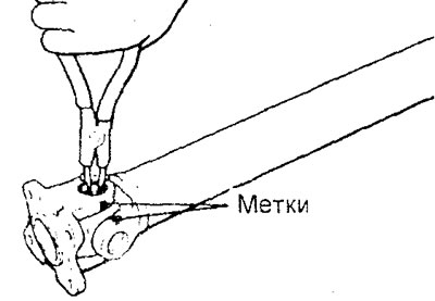
1. Removal of retaining rings.
Before removing the retaining ring, mark the cross and universal joint yoke. Remove the circlips with the special tool.
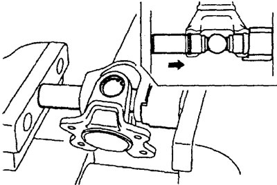
2. Using the special tool, press the bearing out of the cross and universal joint yoke.
Attention: it is not allowed to knock out the bearings when removing, as this can lead to imbalance of the cardan shaft,
4. Remove the flange and yoke of the intermediate cardan shaft
A) Mark the intermediate propeller shaft, flange and yoke,
b) Using the special tool, remove the flange and yoke from the intermediate driveshaft.
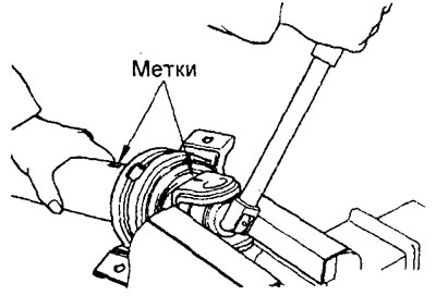
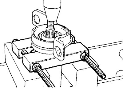
5. Using a press, remove the intermediate support.
6. Remove the hinge.
A) Detach the cover from the hinge.
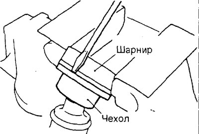
b) Put alignment marks on the outer race, separator and inner race of the hinge.
V) Remove the outer race of the hinge and remove the balls.
Note: Install the balls in their original position.
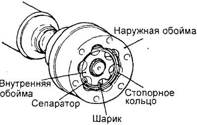
G) Using the special tool, remove the circlip, inner race and cage.
Note: Before changing the grease in the joint, remove the old grease and clean the outer and inner races, the separator and the joint balls.
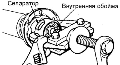
7. Remove a cover of the hinge of a back cardan shaft.
Note: When reinstalling the boot, before removing, wrap the splines of the rear driveshaft with electrical tape.
Examination
1. Check propeller shaft splines for wear or damage.
2. Check the ball grooves on the outer race and inner race of the pivot for uneven wear, damage, or corrosion.
3. Check the surface of the balls for corrosion, wear or other damage.
4. Check the pivot cage for corrosion or damage.
Assembly
- Assembly is carried out in the reverse order of disassembly. When assembling, pay attention to the following operations.
1. Installing the cover of the hinge cardan note of the shaft.
A) Install the clamps on the cover.
b) Wrap the splines of the cardan shaft with electrical tape and install the cover.
2. Installing the hinge assembly.
A) Apply a light coat of special grease to the ball grooves on the outer and inner races of the pivot.
Lubrication - grease from repair kit
b) Install the separator on the inner race of the hinge, aligning the alignment marks, and install the two balls so that they are located in mutually opposite grooves. In this case, both balls should be installed in the same grooves in which they were installed before disassembling the hinge,
V) Install the inner race and separator assembly into the outer race, aligning the alignment marks of their relative position,
G) Install the rest of the balls in the grooves according to their original location.
d) Apply special grease from the repair kit to the joint.
The amount of lubricant - 110±5 g
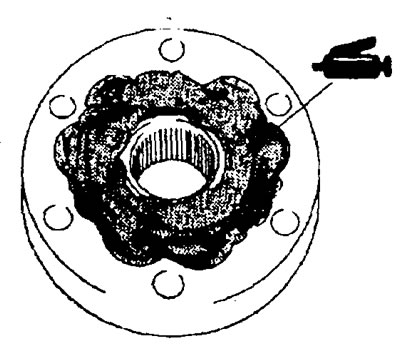
e) Apply a little special adhesive at three points on the surface of the ball grooves, spaced at the same distance from each other around the circumference of the hinge, in which there are grooves for the rubber seal, and then install the rubber seal on the hinge.
Glue - quick-drying glue No. 1741
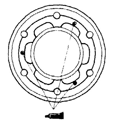
and) Install the joint assembly on the rear propeller shaft, aligning the holes for the mounting bolts. Install a suitable tool head on the inner race of the joint and tap with a plastic-faced hammer to ensure that the joint is firmly seated.
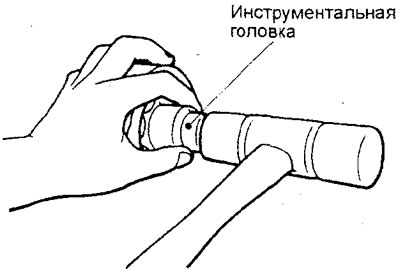
h) Align the bolt holes on the hinge boot with the mounting bolts again, and install the protective boot on the hinge.
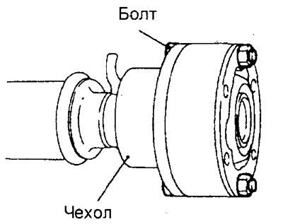
And) Install the flange rubber seal.
3. Installation of a collar of a protective cover.
Attention: position the lock of the protective cover yoke so that it is on the opposite side of the protective cover relative to the protrusions of the cover providing ventilation. Make sure that there is no grease around the protrusions of the protective boot.
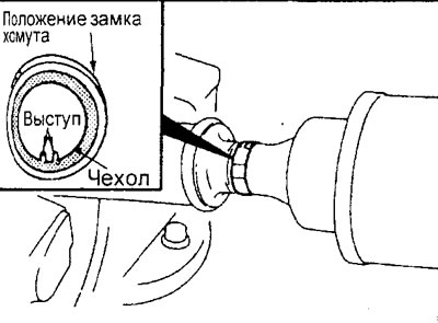
4. Installation of intermediate supports, self-locking nut, flange and fork of the intermediate cardan shaft.
A) Install the intermediate support assembly on the intermediate propeller shaft.
b) Align the previously made alignment marks on the flanges, yoke and intermediate driveshaft.
b) Firmly press the flange, yoke and intermediate supports assembly firmly while tightening the self-locking nuts.
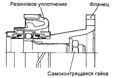
The back of the intermediate driveshaft.
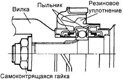
The front of the intermediate cardan shaft.
6. Installation of the universal joint cross and bearings of the universal joint.
A) Apply multipurpose grease to the following parts of the universal joint and bearings.
- Necks and oil collecting grooves of the cross.
- Working edges of seals.
- Needle bearings.
Caution: Do not over-lubricate, as excess lubrication will result in assembly difficulties and improper selection of circlips.
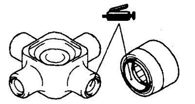
b) Using the special tool, press the bearings into the universal joint yokes in accordance with the following sequence of operations.
- Align the previously made marks of the relative position of the cardan shaft and the universal joint yoke.
- Mount the appropriate mandrel on the special tool.
- Install both bearings in the universal joint yoke and press them in using the special tool.
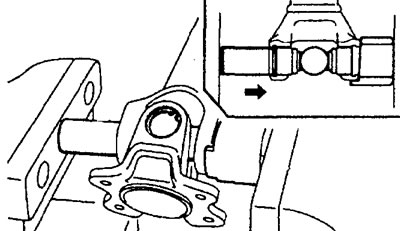
Note:
- When installing the bearing, a groove for the retaining ring should remain.
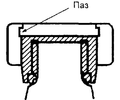
- The bearings will be installed in the position determined by the size of the special tool holder.
7. Installing the retaining ring.
A) Install circlips of the same thickness on both sides of the universal joint yoke.
b) Using a brass drift, press the bearing and cross into the universal joint yoke on one side.
V) Measure the axial clearance of the universal joint bearing (between circlip and bearing) using a probe.
Nominal value - 0.02 - 0.06 mm
Caution: Always install circlips of the same thickness on both sides of the universal joint yoke.
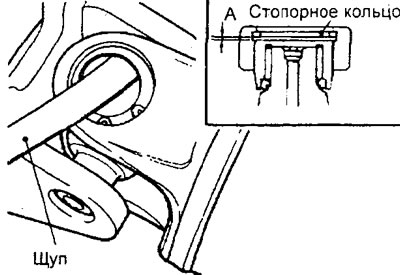
G) If the axial clearance exceeds the maximum allowable value, then adjust it by selecting a retaining ring of suitable thickness.
| Retaining ring thickness, mm | color label |
| 1,02 | — |
| 1,05 | yellow |
| 1,08 | Blue |
| 1,11 | Purple |
| 1,14 | Black |