Disassembly
Note: disassembly is performed in the order of the numbers indicated in the figure "Disassembly and assembly of the drive shaft". When removing parts, pay attention to the following operations.
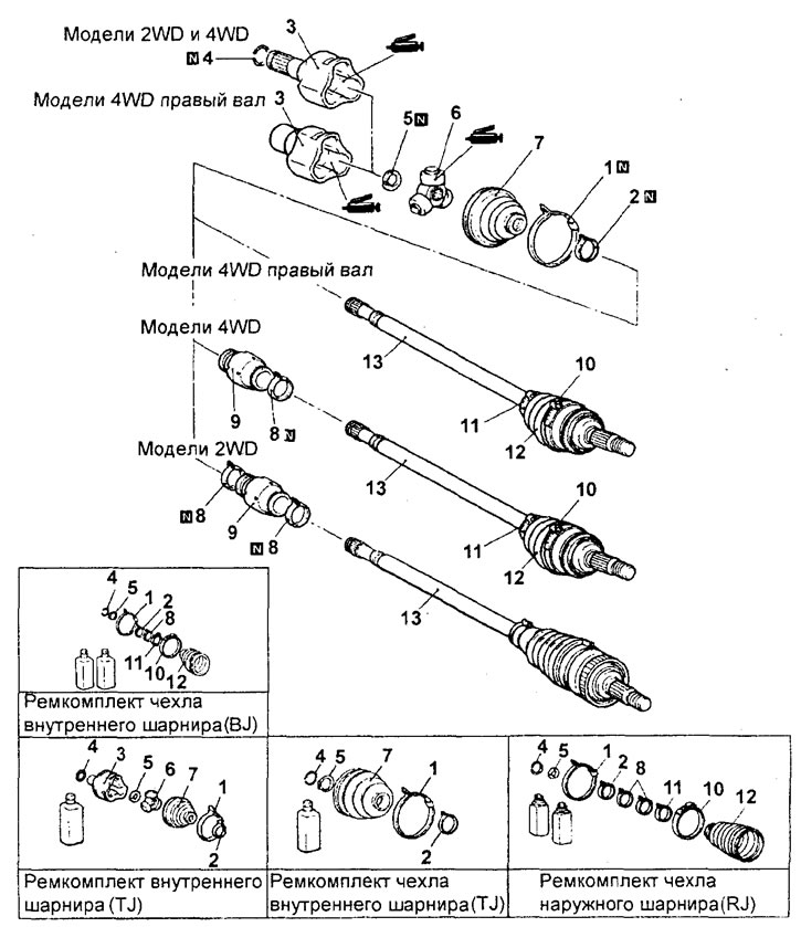
Disassembly and assembly of the drive shaft. 1 - large clamp of the inner joint boot, 2 - small clamp of the inner joint boot, 3 - inner joint collar, 4, 5 - retaining ring, 6 - triple joint, 7 - inner joint boot, 8 - damper clamp, 9 - damper, 10 - large clamp of the outer joint boot, 11 - small clamp of the outer joint boot, 12 - outer joint boot, 13 - drive shaft.
Note: The drive shaft is equipped with an outer joint type (RJ and BJ) and an inner joint type (TJ).
Caution: Do not disassemble the outer hinge.
1. Remove the inner joint cage.
Remove the inner joint cage and remove the grease from the inner cavity of the cage.
Note: Do not allow water or dirt to enter the inner joint race.
2. Remove the inner hinge cover.
a) Remove grease from the splines of the wheel drive shaft.
b) Remove the inner hinge cover.
Note: When reusing the inner joint boot, wrap the splined portion of the shaft with electrical tape to prevent damage to the boot.
Examination
1. Check the drive shaft for damage, deformation or corrosion.
2. Check the splined portion of the drive shaft for excessive wear or damage.
3. Check that the triple joint is not jammed and that there are no signs of excessive wear or corrosion.
4. Check the groove on the inner surface of the inner joint race for signs of wear or corrosion.
5. Check the damper for damage or cracks.
6. Check the hinge covers for damage or cracks.
Assembly
Note: Assembly is performed in the reverse order of disassembly. When performing assembly, pay attention to the following operations.
1. Install the damper.
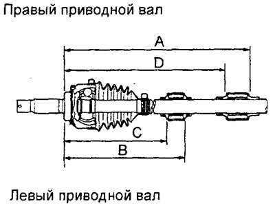
a) Install the damper in the position shown in the figure.
Sedan models:
since 05.2000 (2WD):
with 4G15 engines:
- "A" - 236 mm
- "B" - 469 mm
with 4G93 engines:
- "A" - 239.5 mm
- "B" - 470.5 mm
since 07.2000.
(4WD, with 4G93 engines):
- "A" - 245 ±3 mm
- "B" - 220±3 mm
Station wagon models:
since 11.2000:
2WD:
- "A" - 470.5 mm
- "B" - 239.5 mm
4WD:
- "C" - 220 mm
- "D" —
since 05.2001, with 4G93 engines:
- "C" - 230 mm
- "D" - 415 mm
since 05.2002. (Sport Edition):
2WD:
- "B" - 415 mm
- "C" - 230 mm
4WD:
- "B" - 254 mm
- "C" - 230 mm
b) Tighten the damper clamps.
Attention:
- - Avoid getting grease on the rubber surface of the damper.
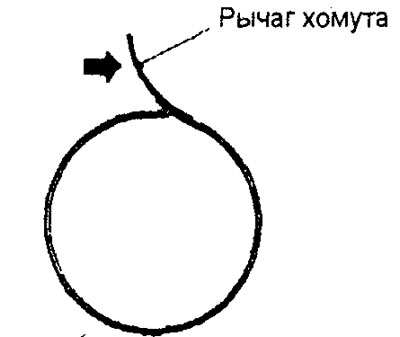
- - The damper and inner joint boot clamps are distinguished by identification numbers applied to the clamp arms. Be especially careful when installing the corresponding clamps.
Identification marks of clamps:
2WD models in saloon body since 05.2000:
- for damper - 31.3 (blue)
- for inner hinge cover - 33 (other)
4WD models, station wagon models (with 4G93 engine (since 05.2001)) and models since 2002. (Sport Edition):
- for damper - 8382
- for inner hinge cover - E687
2. Installing the protective cover of the inner hinge.
Wrap the splined portion of the drive shaft with electrical tape, and then install the small inner joint boot clamp and the inner joint boot.
3. Install the triple joint and inner joint cage.
a) Install the triple joint.
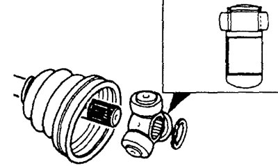
b) Apply special grease from the repair kit between each axle and the inner joint roller.
Recommended grease: from repair kit.
Attention:
- A special grease is used to lubricate the drive shaft joints. Do not mix old and new grease, or different types of grease.
- If the T-joint has been cleaned of grease, be especially careful to apply only the specified grease.
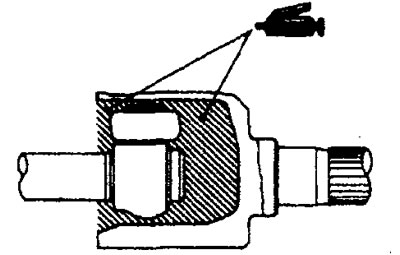
c) After filling the inner joint cage with special consistent grease, install the drive shaft into it and apply grease from the repair kit again.
The material was created based on the website (mitsubishiman.ru)
Amount of grease:
Sedan models:
- 2WD — 125 ±10 g
4WD:
- with 4G15 engines - 95 ±10g
- with 4G93 engines - 105±10g
Station wagon models:
since 11.2000:
- 2WD — 125 ±10 g
- 4WD — 105+ 10 g
since 05.2001, with 4G93 engines:
- left shaft - 115 + 10 g
- right shaft - 120 +10 g
since 05.2002. (Sport Edition):
2WD:
- left shaft - 115 +10 g
- right shaft - 120 +10 g
4WD:
- left shaft - 115 + 10 g
- right shaft - 130 ±10 g
Note: the grease from the repair kit should be divided equally for lubricating the hinge and placing it inside the boot.
Caution: A special grease is used to lubricate the drive shaft joints. Do not mix old and new grease, or different types of grease.
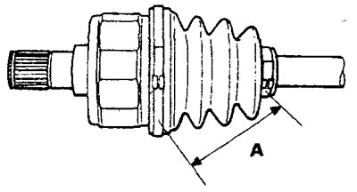
4. Install the small and large inner joint boot clamps.
Install the inner joint boot clamps at the appropriate distance from each other (to ensure the required air volume inside the boot) and then tighten the clamps securely.
Nominal value (A):
Sedan models:
- 2WD — 85+3 mm
4WD:
- with 4G15 engines - 85 ±3 mm
- with 4G93 engines - 90 +3 mm
Station wagon models:
before 05.2001:
- 2WD — 85+3mm
- 4WD — 90+3 mm
since 05.2001.
- with engine 4G93 - 90 +3 mm
Replacing the inner hinge boot clamps
1. Remove the small and large clamps.
Note: When installing, replace the removed clamp with a new one.
2. Remove the inner hinge cover.
3. Install the cover.
a) Install the cover into the groove on the shaft as shown in the figure.
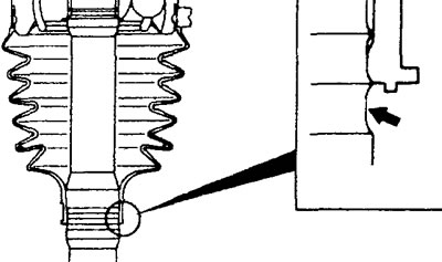
Small clamp (2WD).
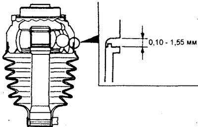
Large clamp (2WD).
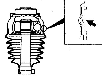
4WD models.
b) Apply special consistent grease from the repair kit to the inside of the cover.
Nominal amount of grease:
Sedan models:
- 2WD models - 110 + 10 g
4WD models:
- Model 1500 - 85 +10 g
- Model 1800 - 95 +10 g
Station wagon models:
- 2WD models - 110 +10 g
- 4WD models - 95 +10 g
4. Turn the adjusting bolt to adjust the special tool to size "A".
Distance "A":
Sedan models:
- Small clamp - 2.9 mm
- Large clamp - 3.2 mm
Station wagon models:
Small clamp:
- 2WD models - 1.6mm
- 4WD models - 2.9mm
Large clamp:
- 2WD models - 1.6mm
- 4WD models - 3.2mm
Note:
- - One turn of the adjusting bolt is approximately 0.7 mm.
- - Do not turn the adjusting bolt more than 1 turn.
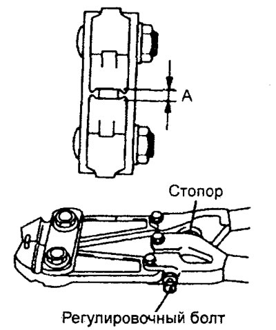
5. Install the clamp as shown in the figure.
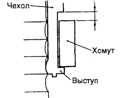
Small clamp (2WD).
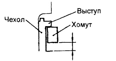
Large clamp (2WD).
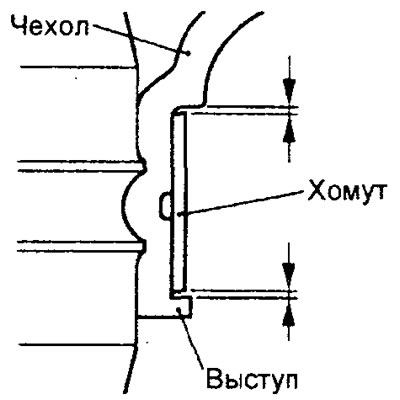
4WD models.
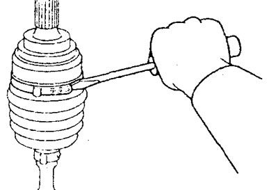
6. Using a special tool, secure the clamp as shown in the figure.
Note:
- - Install the drive shaft vertically.
- - Compress the covers with a special tool until the stopper hits.
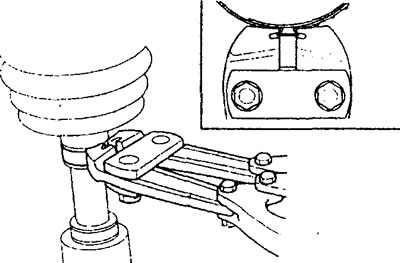
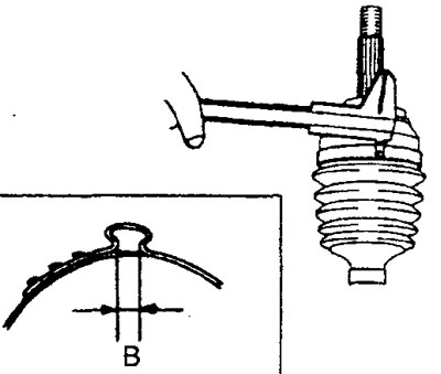
7. Measure the distance "B" as shown in the figure.
Nominal distance:
- 2WD models - 1.0 - 1.5 mm
- 4WD models - 2.4-2.8 mm