Removal
Note:
- Before you start removing parts:
- a) Check the axial clearance of the rear wheel hub bearing,
- b) Check the starting moment of the rear wheel hub bearing.
- Removal is carried out in the order of numbers indicated in the figure "Rear wheel hub".
- When removing parts, pay attention to the following operations.
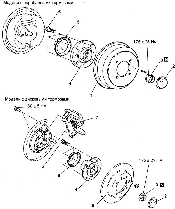
Rear wheel hub (2WD). 1 - brake drum, 2 - cap, 3 - nut, 4 - rear wheel hub, 5 - wheel speed sensor rotor, 6 - hub bolt, 7 - brake caliper, 8 - brake disc.
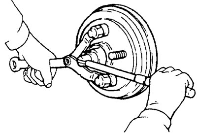
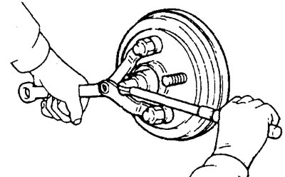
1. Loosen the rear wheel hub nut as shown in the figure.
Caution: Before tightening the rear wheel hub nut, the rear wheel hub bearing must not be loaded with the weight of the vehicle.
Models with drum brakes.
2. Using the special tool, remove the wheel speed sensor rotor as shown in the figure.
Installation
Note:
- - Installation is carried out in the reverse order of removal.
- - When installing the parts, pay attention to the following operations.
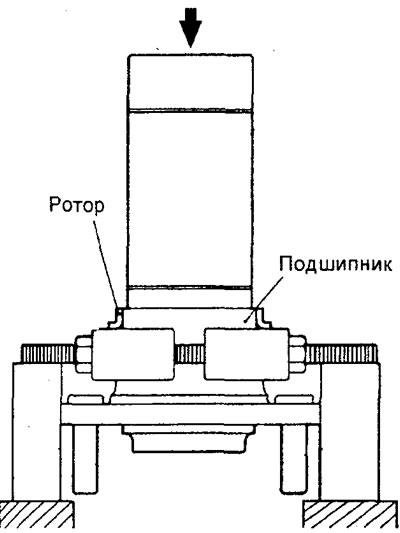
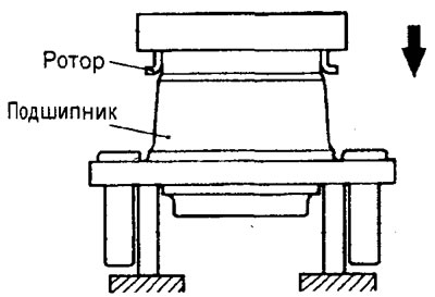
1. Using the special tool, install the wheel speed sensor rotor as shown in the figure.
Note: Do not damage the wheel speed sensor.
2. Tighten the rear wheel hub nut as shown in the figure.
Caution: Before tightening the rear wheel hub nut, the rear wheel hub bearing must not be loaded with the weight of the vehicle.
Models with drum brakes.
Rear drive shafts
Removal and installation
Note:
- - Before starting to remove parts, drain the brake fluid.
- - Removal is carried out in the order of numbers shown in the figure "Rear drive shaft and rear wheel hub (4WD)".
- - Installation is carried out in the reverse order of removal.
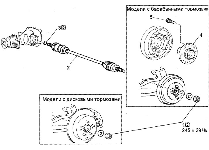
Rear drive shaft and rear wheel hub (4WD). 1 - nut, 2 - drive shaft, 3 - retaining ring, 4 - hub, 5 - hub bolt.
When removing parts, pay attention to the following operations.
a) Using the special tool, disconnect the drive shaft from the rear wheel hub as shown in the figure.
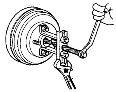
Models with drum brakes.
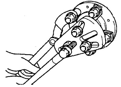
Models with disc brakes.
b) Using a pry bar, remove the drive shaft from the gearbox housing.
Note: Do not damage the gearbox housing oil seal.
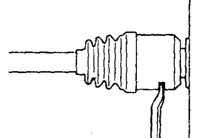
Caution: Be careful not to damage the rotor teeth of the wheel speed sensor. If the rotor teeth become chipped, this will cause the rotor to become deformed, which will result in the wheel speed not being detected correctly and the ABS system not working properly.
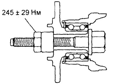
Attention:
- - When loosening the drive shaft mounting nut, the hub bearing must not be loaded with the weight of the vehicle.
- - However, if it is necessary to move the car to another location (the bearing must be loaded with the weight of the car), then temporarily tighten the nut using a special device.
Disassembly
Note:
- - Removal is carried out in the order of numbers indicated in the figure "Disassembling the drive shaft".
- - When removing parts, pay attention to the following operations.
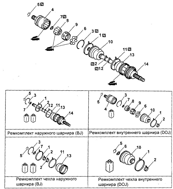
Disassembling the drive shaft. 1 - inner joint boot clamp, 2 - small inner joint boot clamp, 3, 5, 7 - retaining ring, 4 - inner joint cage, 6 - ball, 8 - inner joint cage, 9 - separator, 10 - inner joint boot, 11 - large outer joint boot clamp, 12 - small outer joint boot clamp, 13 - outer joint boot, 14 - outer joint.
Note: The drive shaft is equipped with an outer joint type (BJ) and an inner joint type (DOJ).
Caution: Do not disassemble the outer joint of the drive shaft.
1. Remove the inner joint retaining ring.
a) Remove grease from the inner cavity of the inner joint cage.
b) Remove the retaining ring.
2. Remove the inner joint.
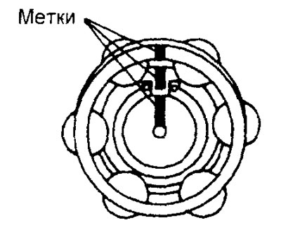
a) Apply timing marks to the drive shaft, inner race and separator.
Note: Do not mark with a sharp object.
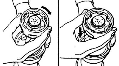
b) Remove six balls.
c) Remove the separator as shown in the figure.
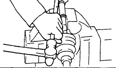
c) Using the special tool, remove the retaining ring.
d) Using a copper rod and a hammer, remove the inner race.
3. Remove the outer hinge covers
a) Remove grease from the drive shaft splines.
b) Remove the outer hinge cover.
Note: When reusing the outer joint boot, wrap the splined portion of the shaft with tape to prevent damage to the boot.
Examination
1. Check the drive shaft joint boots for damage.
2. Check the inner and outer joints of the drive shaft for mobility and the absence of excessive clearances.
3. Check the splined portion of the drive shaft (and hub) for excessive wear or damage.
4. Check that there is no water or foreign particles on the outer hinge.
Assembly
Note:
- - Installation is carried out in the reverse order of removal.
- - When installing the parts, pay attention to the following operations.
1. Install the outer hinge boot.
a) Wrap the splined portion of the wheel drive shaft with electrical tape.
b) Fill the outer joint boot with special consistent grease.
Recommended grease - grease from the repair kit
Quantity - 40 ±10 g
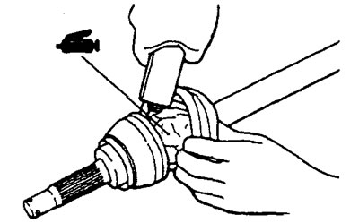
Note:
- - The grease from the repair kit should be divided equally for lubricating the hinge and placing it inside the cover.
- - Do not mix old and new grease, or different types of grease.
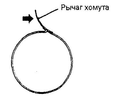
d) Tighten the outer hinge boot clamp.
Attention:
- - To ensure the proper amount of air in the outer joint, the boot must be installed with the drive shaft bend angle at zero.
- - The outer joint boot clamps and the inner joint boot clamps are distinguished by the identification numbers marked on the clamp arms. Be especially careful when installing the corresponding clamps.
Clamp identification numbers:
Sedan models:
large clamp:
Joint type (BJ) - 20 - 128#BJ68L
Joint type (DOJ) - 20 - 66#BJ68
Small clamp
20 - 138#BJ68
Station wagon models:
Large clamp:
- Joint type (BJ) C868L
- Joint type (DOJ) 6668
- Small clamp - D868
2. Install the inner hinge.
a) Using the special tool, install a new snap ring.
b) Align the timing marks and install the inner race onto the drive shaft using a brass rod and hammer.

Caution: Be careful not to damage the inner race.
c) Using the special tool, install a new retaining ring.
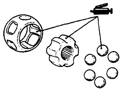
d) Align the timing marks and install the separator and balls onto the inner race.
Note: Apply grease to the parts.
Attention:
- - A special grease is used to lubricate the drive shaft joints. Do not mix old and new grease, or different types of grease.
- - If the inner joint assembly has been cleaned of grease, be especially careful to apply only the specified grease.
3. Install the inner joint sleeve onto the drive shaft.
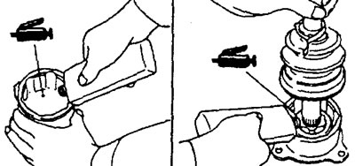
a) Apply grease to the inner joint race and install the inner joint race onto the drive shaft, applying grease to the joint.
Amount of grease - 45 ±10 g
4. Install the inner hinge boot clamps.
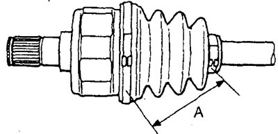
Install the inner CV joint boot clamps at the appropriate distance from each other (to ensure the required air volume inside the boot), and then tighten the clamps securely.
Nominal value (A) - 70 + 3 mm