



Removal
Before you begin removing parts, perform the following operations:
- a) Unscrew the drain plug and drain the oil from the gearbox housing.
- b) Remove the exhaust system components (see chapter "Intake and exhaust systems").
- c) Remove the rear drive shafts (see section "Rear drive shafts").
- d) Remove the rear suspension stabilizer bar (see chapter "Suspension").
The parts are removed in the order of numbers shown in the figure "Removing the rear gearbox". When removing the parts, pay attention to the operation of disconnecting the cardan shaft.
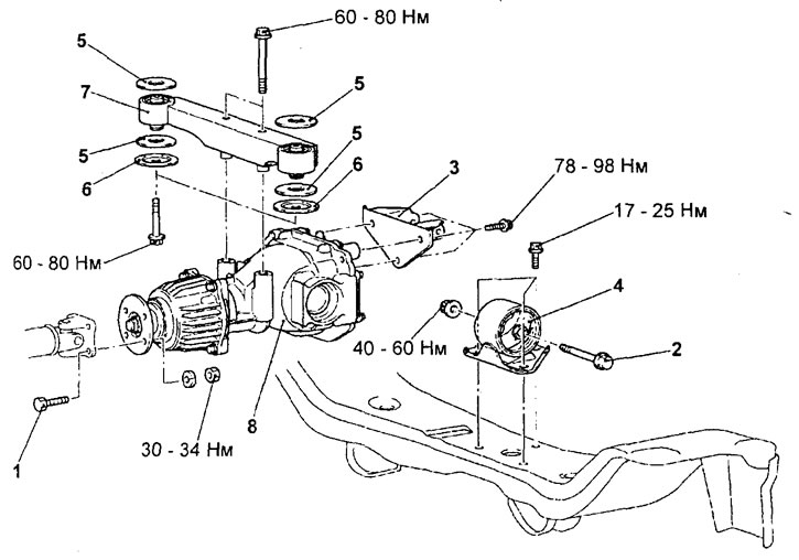
Removal the rear gearbox. 1 - propeller shaft mounting bolt, 2 - support mounting bolt, 3 - gearbox bracket, 4 - gearbox mounting support, 5 - washer, 6 - limiter, 7 - gearbox mounting beam, 8 - gearbox-mounted assembly.
Loosen the bolts and disconnect the cardan shaft, then hang it on the wire without lowering it down.
Examination
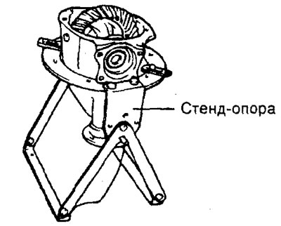
Fix the special device (support stand) in a vice and install the gearbox assembly in the special device.
1. Using a dial indicator, measure the runout of the final drive driven gear.
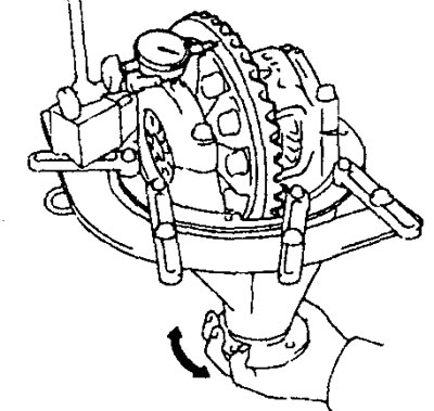
Maximum runout - 0.05 mm
If the runout value does not correspond to the specifications, replace the drive and driven gears as a set.
2. Using a dial indicator, measure the side clearance of the teeth of the driven gear of the main transmission.
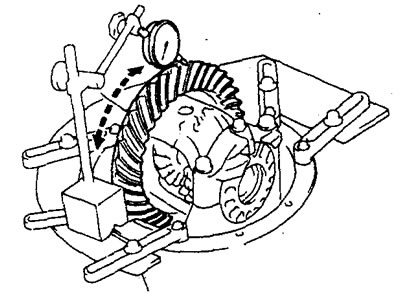
Lateral clearance of teeth - 0.10 -0.15 mm
Note: Measure at least four teeth.
If the side clearance of the driven gear teeth of the main gear is not within the specifications, adjust the preload of the side bearing or repair if necessary.
3. Checking the clearance in the gear engagement of the gearbox.
a) Block the axle gear from turning by inserting a wedge between the gear and the satellite, measure the clearance in the gear engagement of the gearbox using a dial indicator, placing the indicator rod attachment on the satellite.
Note: Measure the clearance at two or more points around the circumference of the satellite.
- Nominal value - 0 - 0.076 mm
- Maximum value - 2 mm
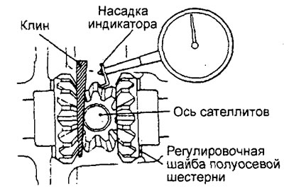
b) If the clearance in the gear engagement is greater than the maximum permissible value, then adjust it by replacing the adjusting spacers of the gearbox housing bearings.
Note: If it is impossible to adjust the clearance in the gearbox gear engagement, replace the axle gears and gearbox satellites as a set.
4. Checking the contact patch in the engagement of the main transmission gears.
a) Apply a thin coat of Prussian blue (or marking paint) to both side surfaces of the driven gear tooth.
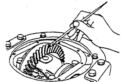
b) Insert a bronze drift (special tool) between the gearbox housing and the gearbox and turn the main drive pinion by hand by the flange, first clockwise (in the forward direction), then counterclockwise. During rotation, load the driven pinion so that the torque applied to the main drive pinion is approximately 2.5 - 2.9 N·m.
Caution: Excessive rotation of the driven gear results in smearing of the contact patch and difficulty in identifying the engagement state.
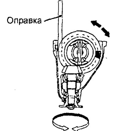
c) Check the contact patch on the teeth of the driven and driving gears of the main transmission.
Note:
- The contact patch test is performed to confirm that the pinion gear position (location of the pinion gear relative to the driven gear) and engagement clearance are adjusted correctly. If necessary, re-adjust the pinion gear position and engagement clearance to achieve the required contact patch in the final drive gear engagement.
- If it is not possible to adjust the contact patch, then the drive and driven gears are worn beyond the maximum permissible values; replace the final drive gear set.
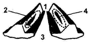
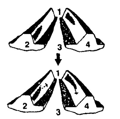
Normal shape of the contact patch. 1 - heel, 2 - leading side, 3 - heel, 4 - trailing side.
d) If the pinion gear is high, the pinion gear is too far from the center of the driven gear. In this case, increase the thickness of the pinion gear adjusting shim to set the pinion gear closer to the center of the driven gear, or move the driven gear away from the pinion gear to adjust the backlash.
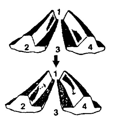
d) If the pinion gear is low, the pinion gear is too close to the center of the driven gear. Reduce the thickness of the shim to set the pinion gear further from the center of the driven gear, or move the driven gear toward the pinion gear to adjust the backlash.
5. Check the oil seal for wear or deformation.
6. Check the bearings for wear or discoloration due to overheating.
7. Check the gearbox housing for cracks.
8. Check the drive and driven gears for wear or cracks.
9. Check the axle gears, satellites and satellite shaft for wear or damage.
10. Check the splined portion of the gearbox axle gears for signs of increased wear or damage.
Disassembly
Note: Before disassembling, please perform the following checks.
- Checking the clearance in the engagement of the main transmission gears.
- Checking the runout of the driven gear of the main transmission.
- Checking the clearance in the gearbox gear engagement.
- Checking the contact patch in the main gear engagement.
When removing parts, refer to the figure "Disassembling and assembling the rear gearbox".
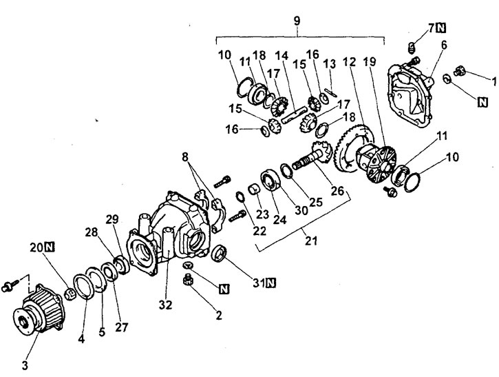
Disassembly and assembly of the rear gearbox. 1 - filler plug, 2 - drain plug, 3 - viscous coupling, 4 - spring washer, 5 - spacer, 6 - gearbox cover, 7 - breather, 8 - bearing caps, 9 - differential, 10 - side bearing spacer, 11 - side bearing, 12 - pinion gear, 13 - lock pin, 14 - satellite axle, 15 - satellite, 16 - satellite thrust washer, 17 - half-axle gear, 18 - half-axle gear thrust washer, 19 - differential housing, 20 - lock nut, 21 - final drive pinion assembly, 22 - adjusting washer, 23 - bushing, 24 - rear bearing inner race, 25 - adjusting washer, 26 - drive gear, 27 - oil seal, 28 - front bearing inner ring, 29 - front bearing outer ring, 30 - rear bearing outer ring, 31 - oil seal, 32 - gearbox housing.
Caution: Be careful when removing the differential housing assembly, perform the removal operation slowly and carefully so as not to drop or damage the outer races of the differential housing bearings.
Note: Keep the right and left differential housing bearings separate to avoid mixing them up during assembly.
Assembly
When installing parts, refer to the figure "Disassembling and assembling the rear gearbox".
Note: Before installing parts into the gearbox housing, pay attention to the lubrication points and the application of locking adhesive (see the figure "Lubrication and sealant application points").
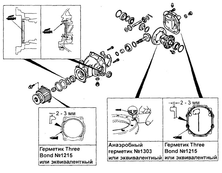
Points for applying lubricant and sealant.
Note: When adjusting the clearance, try to select the minimum number of adjusting shims for each differential housing bearing.
Installation
Installation of parts is carried out in the reverse order of removal.
After completing the installation of the parts, perform the following operations:
- a) Install the rear suspension stabilizer bar (see chapter "Suspension").
- b) Install the rear drive shafts (see section "Rear drive shafts").
- c) Install the exhaust system components (see chapter "Intake and exhaust systems"),
- d) Fill the gearbox housing with oil.
Replacing bushings
1. Using a special tool, press out the bushings.
2. When pressing in the bushings, follow the illustrations provided.
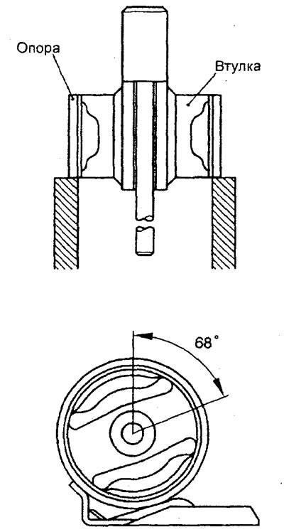
Gearbox mounting support.
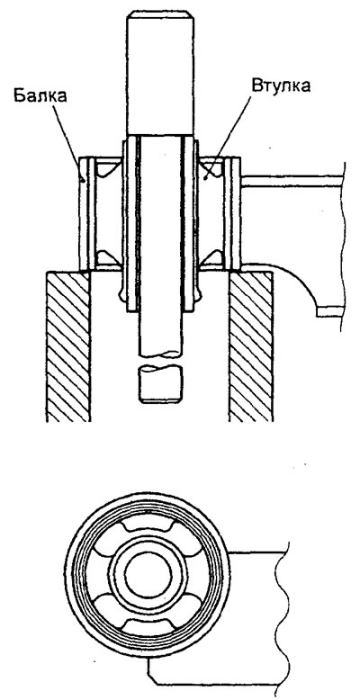
Gearbox mounting beam.