
The procedure for dismantling the rear axle shaft (except a / m 1992-98.)
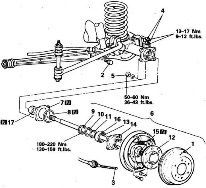
N - to be replaced; 1. Drum; 2. Bolt of fastening of a cable of a manual brake; 3. Handbrake cable tip; 4. Brake tubes; 5. Nuts; 6. Half shaft assembly; 7. Adjusting washers; 8. Ring; 9. Locknut; 10. Pointing washer; 11. Washer; 12. Half shaft; 13. Inner clip; 14. Body; 15, 17. Oil seal; 16. Outer cage
The procedure for dismantling the rear axle shaft (1992-98)
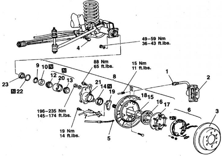
N - to be replaced; 1. Brake tubes; 2. Rear brake; 3. Disk; 4. Handbrake cable bolt; 5. Handbrake cable tip; 6. Hand brake assembly; 7. Speed sensor; 8. Half shaft assembly; 9. Retaining ring; 10. Locking ring bearing; 12. 1st inner bearing race; 13. 2nd inner bearing race; 14, 23. Oil seal; 15. Dirt deflector (for vehicles without ABS); 16. Rotor (on vehicles with ABS); 17. Half shaft; 18. Brake shield; 19. Speed sensor bracket; 20. Outer race of the bearing; 21. Body; 22. Ring
Removal and installation
Cars 1983-91
1. Remove the brake drums.
2. Disconnect the handbrake cable.
3. Turn away 4 nuts of a board of a brake and remove a semiaxle in gathering with a board, the case and the bearing.
4. Remove the ring and shims (for adjusting bearing preload), keeping track of their safety.
5. Press out an epiploon from the back bridge.
6. Loosen the nut, remove the washers and press the bearing with a puller (plates with 4 holes opposite the bearing housing studs).
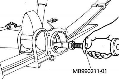
7. Drive the bearing out of the housing and remove the seal.
8. Assembly is carried out in the reverse order.
9. Lubricate the bearing and tighten the nuts and bolts to the correct torque.
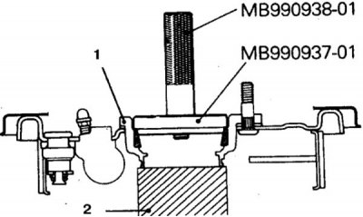
10. Press the bearing races using a special mandrel (1 - body, 2 - emphasis).
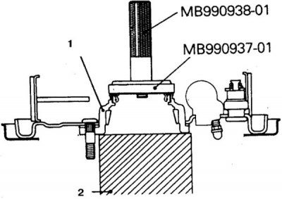
11. Press in the gland using a special mandrel (1 - bearing housing, 2 - stop).
12. Check the axial play of the axle shaft, which should be 0.05–0.20 mm, adjust if necessary (see subsection 9.4.2).
Cars 1992-98
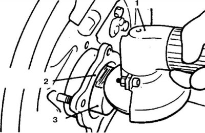
1. Remove the brake caliper and disc, disconnect the handbrake cable.
2. On vehicles with ABS, remove the speed sensor.
3. Remove the semi-axle from the rear axle (use an impact puller if necessary).
4. Remove the retaining ring, knock out the brake shield fastening bolt.
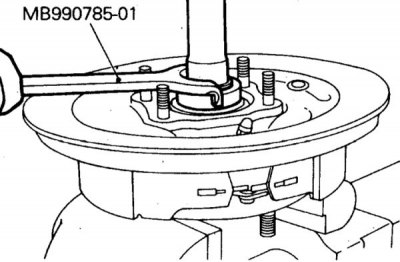
5. To cut the locking ring, one of the pins must be removed (1 - brake shield).
6. Clamp the axle shaft in a vise and carefully cut the bearing locking ring with a hand emery wheel to a thickness of 1–2 mm (1 - hand sander, 2 - bearing housing, 3 - locking ring).
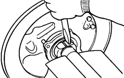
7. After that, knock down the ring with a chisel.
8. Treat the corner of the plate of the MB990861 tool with emery and fix the tool on the axle shaft by picking up the washers and tightening the nuts.
9. Press the half shaft out of the bearing housing.
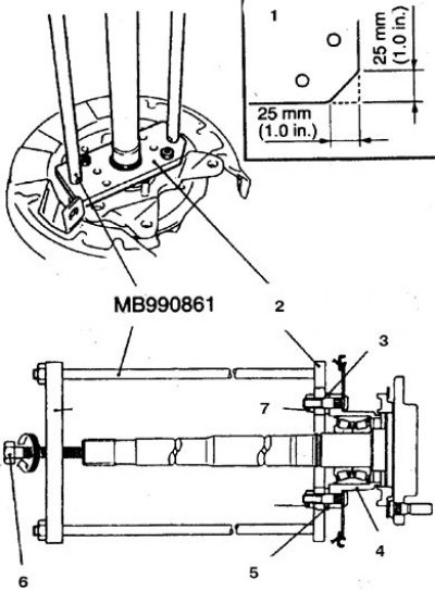
10. Using the MB990861 tool and a press, remove the bearing race from the axle shaft (1 - machined edge of the plate, 2 - plate, 3, 5 - washer, 4 - body, 6 - bolt, 7 - nut).
11. On vehicles with ABS, remove the oil seal and dust cover.
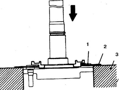
12. On vehicles without ABS, compress the rotor by laying an auxiliary plate 1 mm thick between the rotor and the axle shaft (1, 2 - plate, 3 - support).
Attention! In order not to bend the rotor plate when pressing out, use a mandrel as a support, the diameter of which corresponds to the diameter of the axle shaft flange.
13. Remove the other parts from the axle shaft.
14. Remove the brake shield.
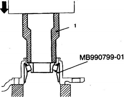
15. Install the removed inner race and use tool MB990799-01 to compress the outer race (1).
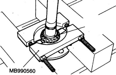
16. Fix the bearing with the tool MB 990560 for knocking out the axle shaft.
17. Remove the bearing housing.
18. Remove the ring and press the oil seal out of the rear axle.
19. Replace worn parts. Those parts that are marked with the letter N are also subject to replacement.
20. Assembly is carried out in the reverse order, taking into account the following.
21. Press in the axle shaft seal using tools MB990932-01 and MB990938-01, or equivalent.
22. Lubricate and press in the bearing outer race with tool MB990890-01.
23. Press the rotor onto the axle shaft using tool MB991388.
24. Press the seal of the bearing housing with the tools MB990936-01 and MB990938-01, having previously lubricated and installed the inner race of the bearing N1.
25. Press the inner race of the N2 bearing onto the axle shaft using the MB990799 tool.
Attention! Both bearing races must be pressed close to each other. Rear axle shafts with self-locking differential have different lengths (the right axle shaft is longer).
26. Press the bearing locking ring onto the axle shaft using the MB990799-01 tool with an initial force of 5 Ts and a final force of 10–11 Ts.
Attention! If the final force is less than specified, replace the axle shaft.
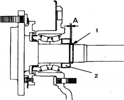
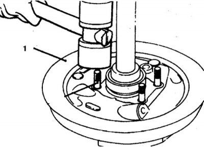
27. After installing the retaining ring, check the gap A between the retaining (1) and shut-off (2) rings, which should not exceed 0.166 mm.
28. Otherwise, select the thickness of the retaining ring using the following thickness color codes: 2.17 mm - none, 2.01 - yellow, 1.85 - blue, 1.69 - pink, 1.53 - red.
29. Tighten all connections to the correct torque.