



Contents: Front wheel hub with manual locking ⤓ The device of the hub with manual…⤓ Hub locking mechanism parts ⤓ Disassembly and assembly ⤓
Front wheel hub with manual locking
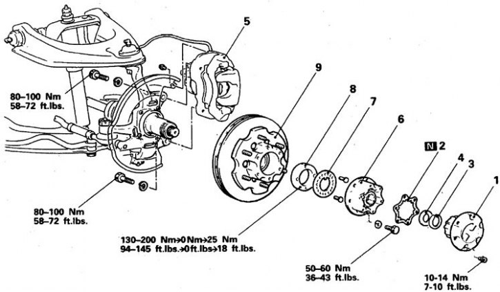
1. Cap; 2. Gasket; 3. Retaining ring; 4. Washer; 5. Front brake; 6. Locking mechanism; 7. Washer; 8. Lock nut; 9. Hub
The device of the hub with manual locking and its switching on and off
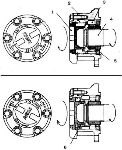
1. Handle; 2. Leash; 3. Coupling; 4. Half shaft; 5. Drive gear of the axle shaft; 6. Spring
Hub locking mechanism parts
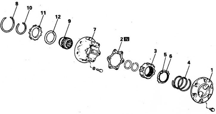
1. Cap; 2. Gasket; 3. Coupling; 4. Spring; 5. Leash; 6. Spring; 7. Body; 8, 10. Retaining ring; 9. Drive gear; 11. Ring gear; 12. Remote laying
The hub is locked by switching the handle to the LOCK position, which causes the splined coupling to move. In the FREE position, the clutch disengages from the hub splines and the wheel rotates freely.
Disassembly and assembly
Cars 1983-88.
1. Raise the front of the vehicle and remove the wheels.
2. Switch the handle to the FREE position and unscrew the 6 hub cap mounting bolts.
3. Remove the retaining ring and washers.
4. Unscrew 2 bolts and remove the front brake, move it to the side and secure it.
5. Unscrew the 6 mounting bolts and remove the hub.
6. Remove the clutch, coil spring, driver ring and snap ring.
7. Using a flat tool, remove the retaining ring at the rear of the hub housing and remove the driven portion of the hub.
8. Remove the snap ring and remove the driven ring gear, spacer shim and hub drive gear.
9. Assembly is carried out in reverse order.
10. Lubricate the ring, drive and driven gears of the hub with SAE J310A or NLGI N3 grease.
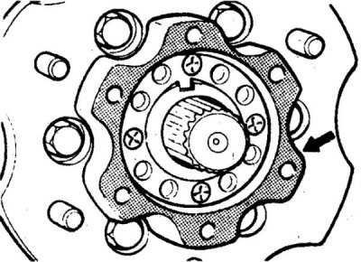
11. When installing the assembled hub, lubricate the contact areas of the gear housing and the hub with 3M ART N 8661 or N 8663 sealant or equivalent (lubrication points are indicated by hatching).
12. Tighten the hub bolts to 50–60 Nm, and the cap bolts to 10–14 Nm.