



Share with friends:
Brake system of the car Mitsubishi Pajero 4

General information
Main brake system This braking system provides a high degree of reliability and durability combined with increased braking efficiency and sensitivity. Parking brake...
Main brake system This braking system provides a high degree of reliability and durability combined with increased braking efficiency and sensitivity. Parking brake...
Technical specifications
Indicators Technical specifications Short wheelbase Long wheelbase Master brake cylinder Type Dual-circuit (with brake fluid emergency level sensor) Inner diameter, mm...
Indicators Technical specifications Short wheelbase Long wheelbase Master brake cylinder Type Dual-circuit (with brake fluid emergency level sensor) Inner diameter, mm...
Basic data for adjustments and control
Indicators Nominal value Maximum permissible value Free travel of brake pedal, mm 3 or less - Distance between brake pedal and floor, mm Short wheelbase 85 or more -...
Indicators Nominal value Maximum permissible value Free travel of brake pedal, mm 3 or less - Distance between brake pedal and floor, mm Short wheelbase 85 or more -...
Checking the brake system
Check all points: Component Procedure Vacuum brake booster Check the operation of the brakes by pressing the brake pedal during a test drive. If the brakes do not work...
Check all points: Component Procedure Vacuum brake booster Check the operation of the brakes by pressing the brake pedal during a test drive. If the brakes do not work...
Troubleshooting
The faults in the brake system and their causes are listed in the table, the numbers in the table are ordered according to the most probable sequence of occurrence of...
The faults in the brake system and their causes are listed in the table, the numbers in the table are ordered according to the most probable sequence of occurrence of...

Special tools
Tool Number and name MUT-III MB991620 Compressor Spring Compressor Adapter MB990964 Tool kit
Tool Number and name MUT-III MB991620 Compressor Spring Compressor Adapter MB990964 Tool kit
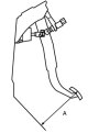
Checking and adjusting the brake pedal
Brake pedal height 1. Remove the mat from under the brake pedal. 2. Measure the height of the pedal position as shown in the figure. If the measured height does not...
Brake pedal height 1. Remove the mat from under the brake pedal. 2. Measure the height of the pedal position as shown in the figure. If the measured height does not...
Checking the brake light switch
Connect a universal tester to the brake light switch and check the brake light switch circuit with the pusher pressed and released. If the pusher is pressed so that its...
Connect a universal tester to the brake light switch and check the brake light switch circuit with the pusher pressed and released. If the pusher is pressed so that its...
Checking the operation of the brake booster
A simple check of the brake booster operation is performed as follows: 1. Start the engine for one or two minutes and turn it off. If the first time you press the brake...
A simple check of the brake booster operation is performed as follows: 1. Start the engine for one or two minutes and turn it off. If the first time you press the brake...

Checking the operation of the check valve
1. Remove the vacuum hose. Caution: Do not disconnect the check valve from the vacuum hose. 2. Check the operation of the check valve using a compressor. Compressor...
1. Remove the vacuum hose. Caution: Do not disconnect the check valve from the vacuum hose. 2. Check the operation of the check valve using a compressor. Compressor...
Checking the brake fluid level sensor
The brake fluid level sensor is normal if the circuit is open when the float surface is above the "MIN" mark and closed when the float surface is below the "MIN" mark.
The brake fluid level sensor is normal if the circuit is open when the float surface is above the "MIN" mark and closed when the float surface is below the "MIN" mark.
Bleeding air from the brake hydraulic system
Caution: Use only recommended brake fluid. Avoid mixing the recommended fluid with other types of brake fluid. Recommended brake fluid: DOT3 or DOT4. Bleeding the master...
Caution: Use only recommended brake fluid. Avoid mixing the recommended fluid with other types of brake fluid. Recommended brake fluid: DOT3 or DOT4. Bleeding the master...

Checking and replacing brake pads
Note: The outer brake pad on the left side of the vehicle has a wear indicator. When the thickness of the pad decreases to 2 mm, the wear indicator comes into contact...
Note: The outer brake pad on the left side of the vehicle has a wear indicator. When the thickness of the pad decreases to 2 mm, the wear indicator comes into contact...

Checking the brake disc
Attention: When servicing disc brakes, special attention must be paid to compliance with the technical requirements for disc brakes, which ensure the normal operation of...
Attention: When servicing disc brakes, special attention must be paid to compliance with the technical requirements for disc brakes, which ensure the normal operation of...

Checking and adjusting the travel of the parking brake lever
1. Pull the parking brake lever with a force of approximately 200 N and count the number of clicks. Nominal value: 6-7 clicks. 2. If the stroke of the parking brake...
1. Pull the parking brake lever with a force of approximately 200 N and count the number of clicks. Nominal value: 6-7 clicks. 2. If the stroke of the parking brake...

Checking the Parking Brake Indicator Light Switch
1. Remove the floor console. 2. Check the circuit between the terminal of the parking brake indicator switch and the switch mounting bolt. The lever is raised...
1. Remove the floor console. 2. Check the circuit between the terminal of the parking brake indicator switch and the switch mounting bolt. The lever is raised...

Removal the brake pedal
1. Remove the bottom panel of the instrument panel. 2. Remove the pin (1) (model with automatic transmission). 3. Disconnect the shift cable connection (2) (model with...
1. Remove the bottom panel of the instrument panel. 2. Remove the pin (1) (model with automatic transmission). 3. Disconnect the shift cable connection (2) (model with...
Installing the brake pedal
Note: When installing, tighten the bolts to the torques specified in the picture . 1. Install the brake pedal and brake pedal mount (11). 2. Install the pedal cover...
Note: When installing, tighten the bolts to the torques specified in the picture . 1. Install the brake pedal and brake pedal mount (11). 2. Install the pedal cover...

Removal the brake booster
1. Drain the brake fluid. 2. Remove the battery (left hand drive model). 3. Remove the air intake hose and air filter assembly. 4. Disconnect the electrical wiring...
1. Drain the brake fluid. 2. Remove the battery (left hand drive model). 3. Remove the air intake hose and air filter assembly. 4. Disconnect the electrical wiring...
Installing a vacuum brake booster
Note: When installing, tighten the bolts to the torques specified in the picture . 1. Install the washer (9). 2. Install the insulator (model with 4M4 engine) (8). 3....
Note: When installing, tighten the bolts to the torques specified in the picture . 1. Install the washer (9). 2. Install the insulator (model with 4M4 engine) (8). 3....

Disassembling the brake booster
1. Remove the filler cap (1). 2. Remove the expansion tank (2). 3. Remove the washer (3). 4. Remove the battery (4). 5. Remove the sealing ring (5). 6. Remove the spring...
1. Remove the filler cap (1). 2. Remove the expansion tank (2). 3. Remove the washer (3). 4. Remove the battery (4). 5. Remove the sealing ring (5). 6. Remove the spring...

Assembly of the brake booster
1. Install the master cylinder and hydraulic block (20). 2. Install the master cylinder piston (19). 3. Install the power piston (18). 4. Install the brake booster inner...
1. Install the master cylinder and hydraulic block (20). 2. Install the master cylinder piston (19). 3. Install the power piston (18). 4. Install the brake booster inner...
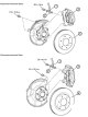
Removal the front disc brake
1. Drain the brake fluid. 2. Disconnect the brake hose connection (1). 3. Remove the gasket (2). 4. Remove the disc brake assembly (3). 5. Remove the brake disc (4).
1. Drain the brake fluid. 2. Disconnect the brake hose connection (1). 3. Remove the gasket (2). 4. Remove the disc brake assembly (3). 5. Remove the brake disc (4).

Installing a front disc brake
Note: When installing, tighten the bolts to the torques shown in the figure. 1. Install the brake disc (4). 2. To measure the rotating resistance force after installing...
Note: When installing, tighten the bolts to the torques shown in the figure. 1. Install the brake disc (4). 2. To measure the rotating resistance force after installing...

Disassembling a disc brake
Short wheelbase model 1. Remove the lower guide pin (1). 2. Remove the upper guide pin (2). 3. Remove the caliper bracket (with brake pads, guides, outer lining) (3). 4....
Short wheelbase model 1. Remove the lower guide pin (1). 2. Remove the upper guide pin (2). 3. Remove the caliper bracket (with brake pads, guides, outer lining) (3). 4....
Disc brake assembly
Short wheelbase model Note: When assembling, tighten the bolts to the torques specified in the picture . 1. Install the clamp (12). 2. Install the brake shoe lining...
Short wheelbase model Note: When assembling, tighten the bolts to the torques specified in the picture . 1. Install the clamp (12). 2. Install the brake shoe lining...

Removal the rear disc brake
1. Drain the brake fluid. 2. Disconnect the brake hose connection (1). 3. Remove the gasket (2). 4. Remove the disc brake assembly (3). 5. Remove the brake disc (4).
1. Drain the brake fluid. 2. Disconnect the brake hose connection (1). 3. Remove the gasket (2). 4. Remove the disc brake assembly (3). 5. Remove the brake disc (4).

Installing a front disc brake
Note: When installing, tighten the bolts to the torques specified in the picture . 1. Install the brake disc (4). 2. To measure the rotating resistance force after...
Note: When installing, tighten the bolts to the torques specified in the picture . 1. Install the brake disc (4). 2. To measure the rotating resistance force after...

Disassembling a disc brake
Short wheelbase model 1. Remove the guide pin (1). 2. Remove the brake shoe and brake shoe lining assembly (2). 3. Remove the brake shoe lining (3). 4. Remove the brake...
Short wheelbase model 1. Remove the guide pin (1). 2. Remove the brake shoe and brake shoe lining assembly (2). 3. Remove the brake shoe lining (3). 4. Remove the brake...
Disc brake assembly
Short wheelbase model Note: When assembling, tighten the bolts to the torques shown in the figure. 1. Install the caliper body (16). 2. Install the piston seal (15). 3....
Short wheelbase model Note: When assembling, tighten the bolts to the torques shown in the figure. 1. Install the caliper body (16). 2. Install the piston seal (15). 3....

Parking brake lever
Removal the parking brake lever 1. Remove the floor console. 2. Remove the bracket (1). 3. Remove the floor console bracket (2). 4. Unscrew the adjusting nut (3). 5....
Removal the parking brake lever 1. Remove the floor console. 2. Remove the bracket (1). 3. Remove the floor console bracket (2). 4. Unscrew the adjusting nut (3). 5....

Parking brake cable
Removal the parking brake cable 1. Remove the floor console. 2. Remove the parking brake pads. Short wheelbase Long wheelbase 3. Disconnect the parking brake cable...
Removal the parking brake cable 1. Remove the floor console. 2. Remove the parking brake pads. Short wheelbase Long wheelbase 3. Disconnect the parking brake cable...

Brake drum of the parking brake system
Removal the brake drum of the parking brake system Short wheelbase car 1. Remove the rear brake drum caliper (1). 2. Remove the rear brake drum (2). 3. Remove the brake...
Removal the brake drum of the parking brake system Short wheelbase car 1. Remove the rear brake drum caliper (1). 2. Remove the rear brake drum (2). 3. Remove the brake...
Anti-lock braking system and stability control system — description
The anti-lock braking system is an active safety device that prevents wheel locking and lateral skidding during emergency braking, ensuring stable control and braking of...
The anti-lock braking system is an active safety device that prevents wheel locking and lateral skidding during emergency braking, ensuring stable control and braking of...
Signs of a faulty anti-lock braking system
Signs Reasons The anti-lock braking system is not working. 1. Check the connection of the diagnostic device. 2. Malfunction of the ignition switch power supply circuit....
Signs Reasons The anti-lock braking system is not working. 1. Check the connection of the diagnostic device. 2. Malfunction of the ignition switch power supply circuit....

Wheel speed sensor
Removal the wheel speed sensor 1. Remove the front wheel speed sensor (1). 2. Remove the rotor guard (2). 3. Remove the front rotor with the drive shaft (3). 4. Remove...
Removal the wheel speed sensor 1. Remove the front wheel speed sensor (1). 2. Remove the rotor guard (2). 3. Remove the front rotor with the drive shaft (3). 4. Remove...

Electronic stability control unit
Removal the electronic stability control unit 1. Remove the center bottom panel. 2. Disconnect the brake booster buzzer connector (1). 3. Remove the brake booster buzzer...
Removal the electronic stability control unit 1. Remove the center bottom panel. 2. Disconnect the brake booster buzzer connector (1). 3. Remove the brake booster buzzer...

Steering wheel sensor
Removal the steering wheel sensor Caution: On vehicles equipped with the Supplemental Restraint System (SRS), before removing the air bag module, refer to CHAPTER -...
Removal the steering wheel sensor Caution: On vehicles equipped with the Supplemental Restraint System (SRS), before removing the air bag module, refer to CHAPTER -...
This section is available on: russian, bulgarian, belarusian, ukrainian, serbian, croatian, romanian, polish, slovak, hungarian
Similar materials for other Mitsubishi models
➤ Chassis and running gear: Brake system Mitsubishi Colt 4 and 5 (1991-2003)
➤ Chassis and running gear: Brake system Mitsubishi Lancer 3 and 5 (1984-1992)
➤ Chassis and running gear: Brake system Mitsubishi Galant 6 and 7 (1987-1998)
➤ Chassis and running gear: Brake system Mitsubishi L200 4 (2005-2014, diesel)
➤ Chassis and running gear: Brake system Mitsubishi Outlander 1 (2003-2008)
➤ Chassis and running gear: Brake system Mitsubishi Space Star (1998-2005)
Link in different formats to this section
TEXTHTMLBB Code
- General information
- User manual
- Troubleshooting
- Maintenance
- Technical specifications
- Power unit
- Engine repair
- Cooling system
- Lubrication system
- Fuel system
- Engine management system
- Intake and exhaust system
- Engine electrical equipment
- Transmission
- Clutch
- Manual gearbox
- Automatic gearbox
- Drive shafts
- Chassis and running gear
- Front suspension
- Rear suspension
- Brake system
- Steering
- Body and interior
- Exterior (external elements)
- Interior (internal elements)
- Doors, locks and windows
- Body dimensions
- Electrical equipment
- Safety system (SRS)
- Air conditioner
- Equipment and devices
- Electrical diagrams
- General information
- User manual
- Seats and seat belts
- Instruments and controls
- Driving and operation
- Maintenance
- Power unit
- Gasoline engines
- Diesel engines
- Ignition system
- Engine electrical equipment
- Cooling and lubrication system
- Power and exhaust system
- Fuel system (gasoline)
- Fuel system (diesel)
- Transmission
- Clutch
- Mechanical gearbox
- Automatic gearbox
- Drive shafts and axles
- Chassis and running gear
- Front suspension
- Rear suspension
- Steering
- Brake system
- Body and interior
- Exterior (external elements)
- Interior (internal elements)
- Doors, locks and windows
- Electrical equipment
- Equipment and devices
- Heater and air conditioner
- Cruise control
- Headlights and lighting
- Electrical circuits