
Share with friends:
Brake system of the car Mitsubishi L200 4
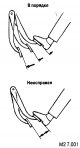
Checking the brake booster
To check the operation of the brake booster, perform the following tests. 1. Start the engine and warm up for 1-2 minutes, then stop it. If the pedal is fully depressed...
To check the operation of the brake booster, perform the following tests. 1. Start the engine and warm up for 1-2 minutes, then stop it. If the pedal is fully depressed...

Air release from master cylinder
The master cylinder does not have a check valve, so (when there is no brake fluid in the master cylinder) air release should be made in the following sequence. 1. Fill...
The master cylinder does not have a check valve, so (when there is no brake fluid in the master cylinder) air release should be made in the following sequence. 1. Fill...
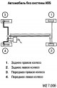
Bleeding air from the brake line
Start the engine and release the air in the sequence shown in the figure.
Start the engine and release the air in the sequence shown in the figure.

Checking and adjusting the spring of the brake force regulator of the rear wheels (without ABS)
Attention: during the test, the car must be unloaded; The vehicle must be parked on a flat, level surface. 1. Press the lever in the direction of the arrow until it...
Attention: during the test, the car must be unloaded; The vehicle must be parked on a flat, level surface. 1. Press the lever in the direction of the arrow until it...

Checking the Rear Wheel Brake Pressure Control Valve by Weight (LSPV)
1. Check the length of the weight sensor spring. 2. Remove the bleed valves from the front and rear brakes and attach pressure gauges. 3. Release the air. 4. Unhook the...
1. Check the length of the weight sensor spring. 2. Remove the bleed valves from the front and rear brakes and attach pressure gauges. 3. Release the air. 4. Unhook the...

Checking and replacing the brake pads of the front brakes
The front brakes have a wear indicator that touches the brake disc and makes a squealing sound when the lining is 1.5mm thick. Attention: in case of replacement of pads,...
The front brakes have a wear indicator that touches the brake disc and makes a squealing sound when the lining is 1.5mm thick. Attention: in case of replacement of pads,...

Checking the Disc Brake Rotor
Attention: in order for the brakes to function properly, the measured values of the brake parts must be within the permitted limits. Before turning the brake disc, check...
Attention: in order for the brakes to function properly, the measured values of the brake parts must be within the permitted limits. Before turning the brake disc, check...
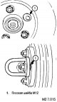
Checking the thickness of the brake disc
1. Using a micrometer, check the disc thickness at 8 locations 45' apart and 10mm from the outer edge of the disc. Standard value: 28.0 nm, limit value: 26.4 mm....
1. Using a micrometer, check the disc thickness at 8 locations 45' apart and 10mm from the outer edge of the disc. Standard value: 28.0 nm, limit value: 26.4 mm....

Checking the flatness of the front brake discs and adjusting
1. Remove the brake assembly and secure it with wire. 2. Temporarily install the disc with the mounting nut. 3. Install the measuring device 5 mm from the edge of the...
1. Remove the brake assembly and secure it with wire. 2. Temporarily install the disc with the mounting nut. 3. Install the measuring device 5 mm from the edge of the...
Checking the thickness of the rear brake pads and drums
Attention: in case of replacement of pads and pads, replace the units on both sides of the car; if the thickness of the pads on the left and right is significantly...
Attention: in case of replacement of pads and pads, replace the units on both sides of the car; if the thickness of the pads on the left and right is significantly...

Removing and installing the brake pedal
Removal order: plug connector (1), brake light switch (2), adjusting mechanism (3), pedal stop (4), clamp (5), clamp support (6), pedal (7), pedal bracket (8)....
Removal order: plug connector (1), brake light switch (2), adjusting mechanism (3), pedal stop (4), clamp (5), clamp support (6), pedal (7), pedal bracket (8)....

Checking the brake light switch
Attach an ohmmeter to the switch terminals. The circuit must be open when the switch is pressed; closed - when released.
Attach an ohmmeter to the switch terminals. The circuit must be open when the switch is pressed; closed - when released.

General description of the braking system
Features of the braking system: 25.4 cm (10 inch) brake booster; 40.64 cm (16") disc brakes on the front wheels, allowing you to achieve a stable braking force and...
Features of the braking system: 25.4 cm (10 inch) brake booster; 40.64 cm (16") disc brakes on the front wheels, allowing you to achieve a stable braking force and...
Brake Specifications
Detail Standard value limit value brake pedal height 178.3-181.3mm Free travel of the brake pedal 3-8mm Gap between brake pedal and floor not less than 75 mm Brake force...
Detail Standard value limit value brake pedal height 178.3-181.3mm Free travel of the brake pedal 3-8mm Gap between brake pedal and floor not less than 75 mm Brake force...

Brake system device
25.4 cm (10 inch) brake booster Dual type brake master cylinder with safety device Brake pedal with pedal kick-out prevention device The brake pedal kick-out prevention...
25.4 cm (10 inch) brake booster Dual type brake master cylinder with safety device Brake pedal with pedal kick-out prevention device The brake pedal kick-out prevention...

Removal and installation of the brake booster
List of elements for drawings M2 7.028 - M2 7.029: 1. TJ level sensor connector. 2. Connecting the master cylinder to the brake line. 3. Master cylinder fixing nut. 4....
List of elements for drawings M2 7.028 - M2 7.029: 1. TJ level sensor connector. 2. Connecting the master cylinder to the brake line. 3. Master cylinder fixing nut. 4....

Dismantling and assembly of the main brake cylinder
Disassembly is carried out in the order shown in the figure. Assembly is carried out in reverse order. 1. Tank cover; 2. Membrane; 3. Pin; 4. Reservoir; 5. Tank seal; 6....
Disassembly is carried out in the order shown in the figure. Assembly is carried out in reverse order. 1. Tank cover; 2. Membrane; 3. Pin; 4. Reservoir; 5. Tank seal; 6....

Removal and Installation of the TL dosing valve depending on the mass (LSPV) (without ABS)
1. Spring support; 2. Spring holder; 3. Bracket; 4. Pipe connection; 5. Valve dosing TJ depending on the mass (LSPV); 6. Bracket; 7. Brake bleed valve Removal is carried...
1. Spring support; 2. Spring holder; 3. Bracket; 4. Pipe connection; 5. Valve dosing TJ depending on the mass (LSPV); 6. Bracket; 7. Brake bleed valve Removal is carried...

Removal and. installation of front brake discs
Note: TJ must be drained before removal. Removal is carried out in the order shown in the figure. Installation is in the reverse order. After installation, it is...
Note: TJ must be drained before removal. Removal is carried out in the order shown in the figure. Installation is in the reverse order. After installation, it is...

Checking the braking force
Use a spring balance to measure the sliding moment of the hub in the forward direction. Attention: do not allow oil, grease and dirt to get on the sliding surfaces of...
Use a spring balance to measure the sliding moment of the hub in the forward direction. Attention: do not allow oil, grease and dirt to get on the sliding surfaces of...
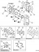
Disassembly and assembly of the front disc brake
In case of disassembly of disc brakes, it is recommended to disassemble and check both brakes (on the right and on the left side). 1. Screw; 2. Caliper bracket with pad,...
In case of disassembly of disc brakes, it is recommended to disassemble and check both brakes (on the right and on the left side). 1. Screw; 2. Caliper bracket with pad,...

Removal and installation of a back drum brake
Note: Before removing, loosen the parking brake adjusting nut and drain the TJ. 1. Brake drum - after removing the drum, disconnect the parking brake cable; 2. Spring...
Note: Before removing, loosen the parking brake adjusting nut and drain the TJ. 1. Brake drum - after removing the drum, disconnect the parking brake cable; 2. Spring...

Dismantling and assembly of the working cylinder of a back drum brake
Disassembly is carried out in the order shown in the figure. 1. Caps; 2. Piston assembly; 3. Piston - clean the piston and brake cylinder with DOT3 or DOT4 brake fluid;...
Disassembly is carried out in the order shown in the figure. 1. Caps; 2. Piston assembly; 3. Piston - clean the piston and brake cylinder with DOT3 or DOT4 brake fluid;...

Anti-lock braking system (ABS) — design description
The ABS system controls the stability and control of the vehicle during hard braking. Vehicles with ABS are equipped with four sensors on the front and rear wheels,...
The ABS system controls the stability and control of the vehicle during hard braking. Vehicles with ABS are equipped with four sensors on the front and rear wheels,...
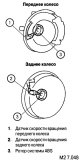
Wheel speed and acceleration sensor
The wheel speed sensors consist of ABS rotors that rotate at the same speed as the wheels, and stationary sensors that detect the rotation speed of the rotors....
The wheel speed sensors consist of ABS rotors that rotate at the same speed as the wheels, and stationary sensors that detect the rotation speed of the rotors....

Measurement of the output voltage of the wheel speed sensor
1. Raise the vehicle and release the parking brake. 2. Turn the locking lever of the ABS-ECU connectors down and disconnect the A-01 connector. 3. Connect a voltmeter or...
1. Raise the vehicle and release the parking brake. 2. Turn the locking lever of the ABS-ECU connectors down and disconnect the A-01 connector. 3. Connect a voltmeter or...

Removal and installation of wheel speed sensors
Attention: to avoid damage to parts, do not touch the protrusion of the sensor (arrow) and to the teeth of the rotor.
Attention: to avoid damage to parts, do not touch the protrusion of the sensor (arrow) and to the teeth of the rotor.
Checking wheel speed sensors
Checking sensors Check the protrusion on the edge of the sensor for dirt and damage. Replace sensor if damaged. Check the resistance between the sensor terminals. Normal...
Checking sensors Check the protrusion on the edge of the sensor for dirt and damage. Replace sensor if damaged. Check the resistance between the sensor terminals. Normal...

Removal and installation of the acceleration sensor
Removing the back panel of the floor console Removal of the back panel of the floor console is made in the sequence specified in drawing M2 7.056. 1. Back panel cover...
Removing the back panel of the floor console Removal of the back panel of the floor console is made in the sequence specified in drawing M2 7.056. 1. Back panel cover...

Checking the acceleration sensor
Disconnect the acceleration sensor connector and attach the special test cable (extension adapter to enable the sensor to be rotated to test voltage when exposed to the...
Disconnect the acceleration sensor connector and attach the special test cable (extension adapter to enable the sensor to be rotated to test voltage when exposed to the...

ABS warning indicator
The ABS warning indicator comes on in the following cases: during the test after turning on the ignition for approximately 3 seconds; in the event of a malfunction in...
The ABS warning indicator comes on in the following cases: during the test after turning on the ignition for approximately 3 seconds; in the event of a malfunction in...

ABS electronic-hydraulic unit
The electronic-hydraulic block is located in the right forward part of a motor compartment. It includes an electric pump, solenoid valves (inputs and outputs - two on...
The electronic-hydraulic block is located in the right forward part of a motor compartment. It includes an electric pump, solenoid valves (inputs and outputs - two on...

TJ pressure control by ABS
The ABS-ECU receives signals from the four wheel speed sensors, determines the speed and acceleration of each wheel, and calculates the vehicle speed. If you depress the...
The ABS-ECU receives signals from the four wheel speed sensors, determines the speed and acceleration of each wheel, and calculates the vehicle speed. If you depress the...

TJ pressure control by EBD system
Electronic brake force distribution (EBD) has its own electronic part with software and uses ABS actuators. The EBD system is designed to monitor and control the rear...
Electronic brake force distribution (EBD) has its own electronic part with software and uses ABS actuators. The EBD system is designed to monitor and control the rear...
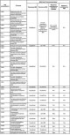
Self-diagnosis and fault codes of the ABS system
Self-diagnostics when switching on the ignition The ABS-ECU performs a self-diagnosis after the ignition is switched on. At the same time, the ABS warning indicator...
Self-diagnostics when switching on the ignition The ABS-ECU performs a self-diagnosis after the ignition is switched on. At the same time, the ABS warning indicator...

Stability System
General information Active Stability Control and Stability Control (ASTC) supplied as optional equipment. It combines the functions of an active stability control system...
General information Active Stability Control and Stability Control (ASTC) supplied as optional equipment. It combines the functions of an active stability control system...

Sensors of the course stability system
Wheel speed sensors See chapter « Anti-Lock Braking System ». Vehicle acceleration and yaw sensor See acceleration sensor in chapter « Anti-Lock Braking System ». The...
Wheel speed sensors See chapter « Anti-Lock Braking System ». Vehicle acceleration and yaw sensor See acceleration sensor in chapter « Anti-Lock Braking System ». The...
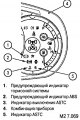
Executive mechanisms of the system of exchange rate stability
Hydro unit In addition to standard ABS systems, ASTC requires in-line valves (one for each diagonal, two in total) and a pressure sensor. Stability indicators The...
Hydro unit In addition to standard ABS systems, ASTC requires in-line valves (one for each diagonal, two in total) and a pressure sensor. Stability indicators The...
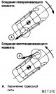
The principle of operation of ASC and ATC systems
The principle of operation of the active stability control system (ASC) The ASC system controls the turning moment with the help of the brake mechanism of each wheel....
The principle of operation of the active stability control system (ASC) The ASC system controls the turning moment with the help of the brake mechanism of each wheel....

Safe Mode and Stability Diagnostics Functions
The ASTC-ECU regularly checks the incoming and outgoing signals. If an error is detected, the ECU gives a signal and the ASC indicator lights up. Depending on the nature...
The ASTC-ECU regularly checks the incoming and outgoing signals. If an error is detected, the ECU gives a signal and the ASC indicator lights up. Depending on the nature...

Acceleration and yaw sensor — removal and installation
In order to get to the acceleration and yaw sensor, you need to remove the rear and front floor panels (see « Removal and installation of the acceleration sensor » in...
In order to get to the acceleration and yaw sensor, you need to remove the rear and front floor panels (see « Removal and installation of the acceleration sensor » in...
Removal and installation of the steering wheel position sensor
Attention: before starting work, disconnect the wire from the negative terminal of the battery, wait one minute and insulate them with adhesive tape; airbag modules with...
Attention: before starting work, disconnect the wire from the negative terminal of the battery, wait one minute and insulate them with adhesive tape; airbag modules with...
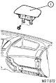
Removal and installation of a pillow of safety of the forward passenger
Removal is carried out in the following order. Glove box cover. 1. Front Passenger Airbag Module (see below). Installation is carried out in the reverse order with the...
Removal is carried out in the following order. Glove box cover. 1. Front Passenger Airbag Module (see below). Installation is carried out in the reverse order with the...

Removal and installation of an airbag of the driver and a rotating joint
Removing the driver's airbag and rotating contact joint is carried out in the following order (see fig. M2 7.073). 1. Lid (see below). Horn plug. Driver Airbag Module...
Removing the driver's airbag and rotating contact joint is carried out in the following order (see fig. M2 7.073). 1. Lid (see below). Horn plug. Driver Airbag Module...
This section is available on: russian, bulgarian, belarusian, ukrainian, serbian, croatian, romanian, polish, slovak, hungarian
Similar materials for other Mitsubishi models
➤ Chassis and running gear: Brake system Mitsubishi Colt 2 and 3 (1983-1993)
➤ Chassis and running gear: Brake system Mitsubishi Lancer 9 (2000-2007, petrol)
➤ Chassis and running gear: Brake system Mitsubishi Galant 6 and 7 (1987-1998)
➤ Chassis and running gear: Brake system Mitsubishi Outlander 1 (2003-2008)
➤ Chassis and running gear: Brake system Mitsubishi Pajero 1 and 2 (1982-1999)
➤ Chassis and running gear: Brake system Mitsubishi Space Star (1998-2005)
Link in different formats to this section
TEXTHTMLBB Code
- General information
- User manual
- Maintenance
- Power unit
- Diesel engine
- Lubrication system
- Fuel system
- Control system
- Transmission
- Clutch
- Mechanical gearbox
- Transfer case
- Front axle
- Rear axle
- Chassis and running gear
- Car suspension
- Steering
- Brake system
- Body and interior
- Exterior (external elements)
- Interior (internal elements)
- Doors, locks and windows
- Electrical equipment
- Equipment and devices
- Electrical circuits
MitsubishiMan.ru © 2018–2024 • Mobile version • Articles about Mitsubishi • Contacts • Sitemap: EN BG BY UA RS HR RO PL SK HU • Site search • Bookmark
Colt 2 and 3 (1983-1993) · Colt 4 and 5 (1991-2003) · Colt 5 (1995-2003) · Lancer 3 and 5 (1984-1992) · Lancer 9 (2000-2007) · Galant 6 and 7 (1987-1998) · L200 4 (2005-2014) · Outlander 1 (2003-2008) · Pajero 1 and 2 (1982-1999) · Carisma (1995-2004) · Space Star (1998-2005) ·
Colt 2 and 3 (1983-1993) · Colt 4 and 5 (1991-2003) · Colt 5 (1995-2003) · Lancer 3 and 5 (1984-1992) · Lancer 9 (2000-2007) · Galant 6 and 7 (1987-1998) · L200 4 (2005-2014) · Outlander 1 (2003-2008) · Pajero 1 and 2 (1982-1999) · Carisma (1995-2004) · Space Star (1998-2005) ·