Contents: Removal ⤓ Installation ⤓
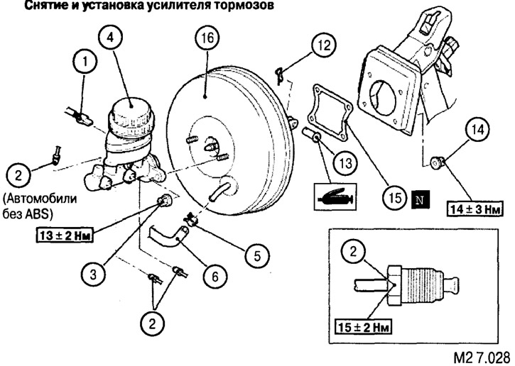
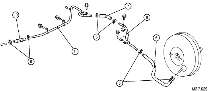
List of elements for drawings M2 7.028 - M2 7.029: 1. Brake fluid level sensor connector. 2. Master cylinder to brake line connection. 3. Master cylinder fastening nut. 4. Brake master cylinder: Before installation, check and, if necessary, adjust the stroke of the brake booster valve pushrod (see below). 5. Hose clamp. 6. Vacuum hose with built-in check valve. 7. Vacuum hose B. 8. Vacuum pipe B. 9. Hose clamp. 10. Vacuum hose A. 11. Vacuum pipe A. 12. Pin clamp. 13. Pin. 14. Brake booster fastening nut. 15. Seal. 16. Brake booster.
Removal
Note: Brake fluid must be drained before removal.
Removal is carried out in the order shown in figures M2 7.028 - M2 7.029.
Installation
Installation is performed in the reverse order. After installation, it is necessary to fill the brake system with brake fluid and release air.
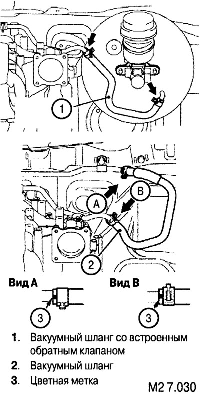
Connecting the vacuum hose and clamp
Install the vacuum hose and clamp so that the color marks on them are positioned as shown in the illustration.
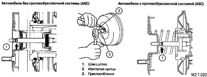
Checking and adjusting the valve tappet stroke
For a more accurate check, apply a negative pressure of 66.5 kPa to the brake booster. In this case, the standard values (A) are:
- for vehicles without traction control system (ASC): 9.925-10.175 mm;
- for vehicles with traction control system (ASC): 6.675-6.925 mm.
Without 66.5 kPa pressure applied to the brake booster, the values (A) are:
- for vehicles without traction control system (ASC): 8.925-9.175 mm;
- for vehicles with traction control system (ASC): 7.675-7.925 mm.
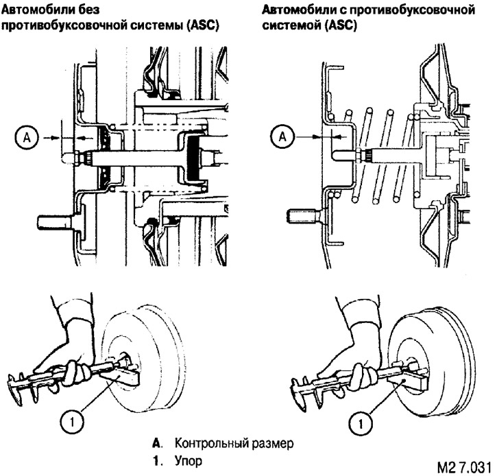
If the stroke of the piston rod exceeds the specified value, adjust it by turning it with a special tool while holding the piston rod spline with curved pliers.