



The EBD system, guided by data on the vehicle's deceleration rate and wheel slip, controls the electromagnetic valves, increasing or decreasing the brake fluid pressure in the rear brakes. Thus, EBD improves both the vehicle's braking force and its controllability and stability. Also, thanks to EBO, the driver does not need to press the brake pedal harder in a more loaded vehicle or when driving on a slippery surface.
Thanks to the optimal distribution of braking forces between the axles, the load on the front brakes is reduced, which increases the service life of the brake pads and discs.
Specifications
| Position | Specification |
| ABS control method | 4 sensors |
| Number of teeth of front and rear ABS sensor rotors | 47 |
| Wheel speed sensor type | electromagnetic |
| Gap between sensor and front wheel rotor (non-adjustable) | 0.25-1.40 mm |
| Gap between sensor and rear wheel rotor (non-adjustable) | 0.18-0.92 mm |
ABS Controls
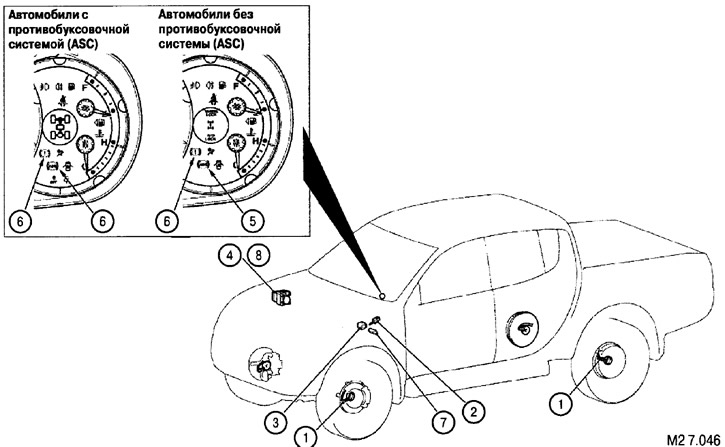
ABS system controls shown in Fig. M2 7.046
| № | Part name | Function Description |
| Sensors | ||
| 1 | Wheel speed sensors | Determines the rotation speed of each wheel |
| 2 | Brake light switch | When the brake pedal is pressed, the brake light turns on |
| 3 | Acceleration sensor (all-wheel drive) | Determines the acceleration in the direction of vehicle movement |
| Executive devices | ||
| 4 | Electronic-hydraulic unit | Controls electromagnetic valves |
| 5 | ABS Malfunction Warning Light | Turns on in case of a system malfunction |
| 6 | Brake system malfunction warning light | Turns on in case of a system malfunction |
| 7 | Diagnostic connector | Serves to connect diagnostic devices |
| 8 | Electronic control unit of the anti-lock braking system (ABS-ECU) | Processes data from sensors and controls actuators. Performs self-diagnostics |
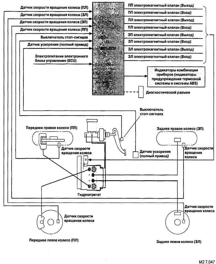
Block diagram of the ABS system
(The original article is on: mitsubishiman.ru)