General information
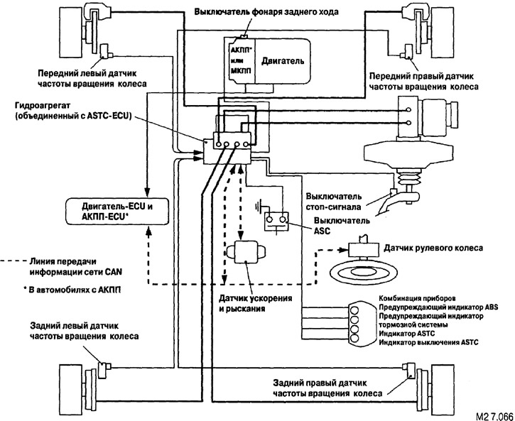
Active Stability and Traction Control (ASTC) is available as optional equipment. It combines the functions of the Active Stability Control (ASC) and Active Stability Control (ASTC).
When the ATC system detects slippage of the drive wheel, it automatically applies the brake of that wheel. On the other hand, ATC reduces engine power and prevents slippage when it detects that the engine torque is too high for the road surface condition (the inclination angle is also determined) on which the vehicle is moving.
If ASC determines that the vehicle is in a dangerous position, it reduces engine power and independently applies the brakes on all four wheels, monitoring the vehicle's behavior and preventing a critical situation.
The system is also equipped with a safe mode function.
To reduce the number of wires and improve the quality and speed of information transfer, communication with the electronic control unit (ECU) is implemented via a controller area network (CAN).
On vehicles with ASC, the ASTC-ECU also controls the anti-lock braking system (ABS).
Placement of system elements
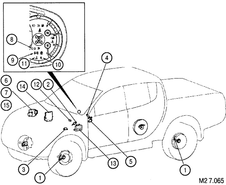
Elements of the electronic stability control system
Original version of the article on the website mitsubishiman.ru
| № | Detail | Function Description |
| 1 | Wheel speed sensor | Detects wheel speed and reports it to the ASTC-ECU |
| 2 | Brake light switch | Tells the ASTC-ECU when the brake pedal is depressed |
| 3 | Acceleration and yaw rate sensor | Detects longitudinal and lateral acceleration as well as vehicle yaw and reports to the ASTC-ECU |
| 4 | Steering wheel sensor | Detects the position of the steering wheel and reports it to the ASTC-ECU |
| 5 | ASC switch | Sends a signal to the ASTC-ECU to turn the active stability control system on or off |
| 6 | Pressure sensor | Built into the hydraulic unit; detects brake fluid pressure in the master cylinder and reports it to the ASTC-ECU unit |
| 7 | Hydro unit | Controls the electromagnetic valves in accordance with signals from the ASTC-ECU unit, monitoring the brake pressure of each wheel |
| 8 | Brake warning indicator | Lights up when there is a fault in the system |
| 9 | ABS warning light | Lights up when there is a fault in the system |
| 10 | ASTC indicator | Flashes when the system is running. Lights up when there is a fault |
| 11 | ASTC off indicator | Lights up when the system is not working or is faulty. Flashes when overheating occurs |
| 12 | Diagnostic connector | For diagnostics using a special device |
| 13 | Automatic transmission-ECU (only in cars with automatic transmission) | Reports the status of the gearbox to the ASTC-ECU unit |
| 14 | Engine-ECU | Receives signals from the ASTC-ECU to control engine power |
| 15 | Automatic stability control and electronic control unit (ASTC-ECU) | Controls actuators based on sensor signals |
| Manages self-diagnosis and safe mode | ||
| Manages diagnostics via the diagnostic connector |
Wiring diagram