



Contents: Precautionary measures ⤓ Checking connectors ⤓ Checking the electrical wiring ⤓ Connector designations ⤓ Checking the circuit when the fuse…⤓ Troubleshooting intermittent problems ⤓
Attention: Please read the section "Safety measures when performing work" chapters "Maintenance and general check and adjustment procedures".
Precautionary measures
1. Before you start troubleshooting the fuel injection system, check that the engine settings are correct (see chapter "Maintenance and general check and adjustment procedures").
2. Before disconnecting the electronic control unit connectors, it is necessary to disconnect the electrical power either by using the ignition key or by removing the terminals from the battery.
Caution: Be sure to read diagnostic codes before disconnecting the battery cables.
3. When installing the battery, do not confuse the polarity of the wires connected to its terminals.
4. Do not subject fuel injection system components, especially the electronic control unit, to impact.
5. Be careful when troubleshooting, with a large number of transistor circuits, even a slight careless touch of the terminals can lead to serious damage.
6. Do not open the cover of the electronic control unit housing.
7. When working in rainy weather, protect electronic control units from water. The same should be done when washing the engine.
8. Be careful when disconnecting and connecting electrical wiring connectors.
9. To avoid misfires after repair, take the following precautions.
a) Check the reliability of the connection of the wires to the battery terminals.
b) Work carefully with high-voltage wires.
c) After completing the repair work, make sure that all ignition system wires are correctly and securely connected.
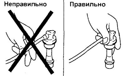
Checking connectors
1. Connecting and disconnecting connectors.
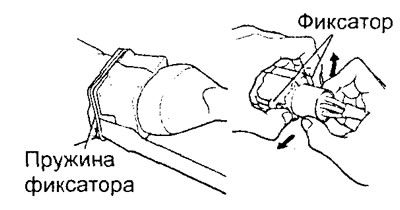
a) When disconnecting, loosen the lock by pressing on the spring and pull out the connector, holding it by the body.
b) When connecting, insert the connector fully and make sure it is locked.
[The original material is posted on the website: MITSUBISHIMAN]
2. Checking the quality of the connection in the connector.
Warning: Malfunctions in the electronic control system may be caused by incorrect connection of the electrical wiring connectors. However, when checking the system, the malfunction symptom may disappear after repeated disconnection and connection of the connectors. Possible causes of such malfunctions are:
- - The connector is disconnected or the connector is not connected correctly.
- - Loss of connector pins.
- - Poor contact in the connector due to excessive tension on the wiring in the connector.
- - Weak contact due to corrosion of the connector terminals, foreign particles getting inside.
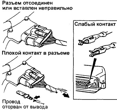
a) If the terminal stopper in the connector is damaged, the terminals may fall out from the back of the connector, even if the connector is connected. Therefore, it is necessary to carefully tug each wire from the back of the connector and make sure that the terminals do not fall out.
b) To check the reliability of the contact between the terminals, use a special tool. The force of disconnecting the terminal should be at least 1 N.
3. Checking the connector terminals.
Attention:
- Never force the probe into the connector, as this may damage the pin or cause poor contact in the connector. If the probe cannot be inserted into a connector that is too small (electronic control unit, etc.), use an ultra-thin probe.
- Be very careful when checking to avoid short-circuiting the terminals. Short-circuiting the terminals can cause damage to the circuits inside the electronic control unit.
4. Features of testing the output of sealed connectors.
Caution: When testing circuits with sealed (waterproof) connectors, it is recommended to use a test lead harness.
a) If the test wire harness is missing, carefully remove the protective cover.
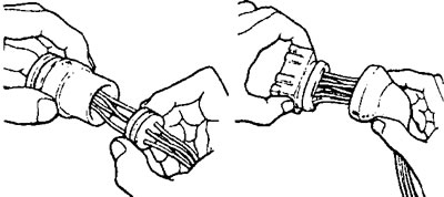
b) When checking resistance, current or voltage, always insert the tester probe from the wire side.
Caution: Never insert the probe directly into the connector from the wire side through the protective cover, as this will result in a breach of the connector seal and corrosion of the contacts.
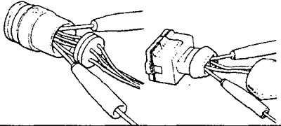
c) After checking, firmly install the protective cover on the connector.
Checking the electrical wiring
1. When checking the wiring harness for an open circuit when the ends of the wire being checked are significantly separated from each other, use a wire with an alligator clip to connect one end of the wire to ground, and then check for a closed circuit between the other end of the wire and ground. If the circuit is open, repair the wiring.
Note: However, when checking a power line wire for an open circuit, check for a closed circuit directly between both ends of the wire, without using an alligator clip to connect one end of the wire to ground.
2. When checking the circuit for a short circuit (to ground), disconnect one end of the wire and check for an open circuit between ground and the other end of the wire. If there is a short circuit, repair the wiring.
Note: As a general rule, use an analog ohmmeter or multimeter when checking the condition of a circuit.
If the wiring is normal, but the voltage (power) supplied to the sensor differs from normal, then replace the electronic engine control unit with a known good unit and repeat the check.
Note: Generally, when checking voltage, use a digital voltmeter (or multimeter), however, when checking voltage in the power transistor circuit, you should change to an analog voltmeter.
Connector designations
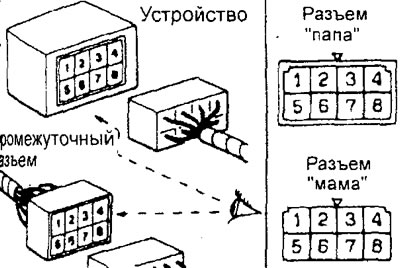
The numbering of the connector terminals from the device side (for the intermediate connector, from the male connector side) is indicated when looking at the connector from the terminal side (from the side where the connector is connected).
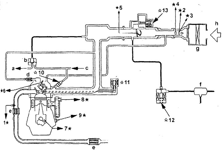
General diagram of the fuel injection system (MPI, engine 4G93).1 - oxygen sensor, 2 - mass air flow sensor, 3 - absolute (barometric) pressure sensor, 4 - intake air temperature sensor, 5 - throttle position sensor, 6 - camshaft position sensor, 7 - crankshaft position sensor, 8 - engine coolant temperature sensor, 9 - knock sensor, 10 - fuel injector, 11 - EGR valve servo, 12 - canister purge solenoid valve, 13 - idle speed controller servo, a - into fuel tank, b - fuel pressure regulator, c - from fuel pump, d - positive crankcase ventilation valve, e - catalytic converter, f. canister, g - air filter, h - air.
Note: The signals of the components marked with " ☆ " are used by the electronic control unit (signals from the ignition switch ("ST" and "IG" terminals), power line, vehicle speed sensor, air conditioner switch, start prohibition switch, power steering fluid pressure switch, air conditioner load signal, generator "FR" terminal are also used); marked with " ☆ " are actuators (together with the fuel pump relay, the main injection system relay, the air conditioning compressor electromagnetic clutch relay, the "CHECK ENGINE" indicator, the ignition coil, the electric fan controller, the self-diagnosis circuit, the "G" terminal of the generator, the heating element of the oxygen sensor, the tachometer).
Checking the circuit when the fuse blows
1. Remove the fuse and measure the resistance between the ground and the load contact of the fuse.
a) Set the switches of all circuits related to this fuse to the closed position.
b) If the resistance is almost zero, then a short circuit occurs in the circuit between the switches and the load.
c) If the resistance is greater than zero, then there is currently no short circuit. However, the instantaneous short circuit caused the fuse to blow.
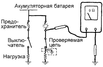
2. The main causes of short circuits are:
- a) Pinching of the wire by a body part.
- b) Damage to insulation due to wear or overheating.
- c) Water entering the connector or circuit,
- d) Human error (erroneous short circuit, etc.).
Troubleshooting intermittent problems
1. Intermittent faults (where the fault symptom may not reappear) often occur under certain conditions and if these conditions can be established, the cause of the fault can be easily determined. To determine the conditions under which the fault occurs, information about the driving conditions, weather conditions, frequency of occurrence and fault symptoms are first needed.
2. Perform a simulation test to reproduce the conditions for the malfunction to occur.
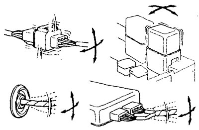
a) When the root cause of the fault is probably vibration then:
- - Gently shake the connector up and down, right and left.
- - Gently shake the wire up, down, right and left.
- - Gently shake each sensor, relay, etc. by hand.
- - Gently shake the wire harnesses located on the suspension and other moving parts.
Note: if any wire shows signs of mechanical damage (severe bending, breakage, insulation cut, etc.), then a new wire must be connected in its place.
b) When the root cause of the fault is likely to be overheating, use a hair dryer to heat the component where the fault is suspected to occur.
Caution: Do not heat system components above 80°C.
c) When the main cause of the malfunction is probably increased resistance in the electrical circuits, set all electrical switches (including the headlight switches and rear window defogger switch) to the "ON" position.
d) If the malfunction symptom does not reoccur even after performing the above checks, troubleshooting should be temporarily discontinued.