



Removal and installation
1 Before removing parts, release residual pressure from the high-pressure fuel line.
The parts are removed in the order of the numbers indicated in the figure "Removing the injectors".
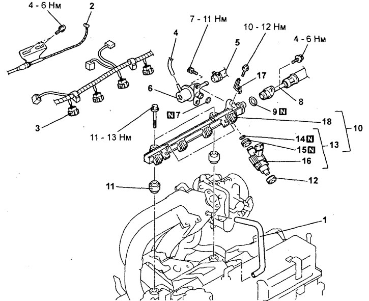 Removal injectors (engine 4G15).1 - Positive crankcase ventilation hose connection, 2 - Accelerator pedal cable connection, 3 - Injector connector, 4 - Vacuum hose connection, 5 - Fuel return hose connection, 6 - Fuel pressure regulator, 7 - O-ring, 8 - High-pressure fuel hose connection, 9 - O-ring, 10 - Fuel rail assembly, 11 - Insulator, 12 - Insulator, 13 - Injector assembly, 14 - O-ring, 15 - Sealing ring, 16 - Injector, 17 - Injector wire harness retainer bracket, 18 - Fuel rail.
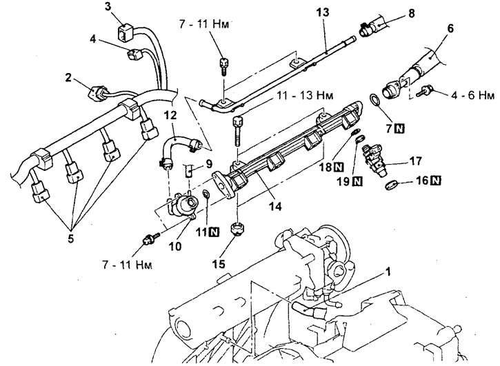 Removal injectors (engine 4G93).1 - Positive crankcase ventilation hose connection, 2 - EGR valve servo connector, 3 - Throttle position sensor connector, 4 - Idle speed control servo connector, 5 - Injector connector, 6 - High-pressure fuel hose connection, 7 - O-ring, 8 - Fuel return hose connection, 9 - Vacuum hose connection, 10 - Fuel pressure regulator, 11 - O-ring, 12 - Fuel hose, 13 - Fuel return pipe, 14 - Fuel rail, 15 - Insulator, 16 - Insulator, 17 - Injector assembly, 18 - O-ring, 19 - Sealing ring.
When removing parts, pay attention to the operation of removing the heated manifold.
Caution: Be careful when placing the fuel manifold in the top with the injectors, do not drop the injectors.
Installation is carried out in the reverse order of removal.
When installing the parts, pay attention to the installation operation of the injectors, fuel pressure regulator (flange) and high-pressure fuel hose (flange).
a) Apply a small amount of clean engine oil to the element's O-ring.
Caution: Be careful not to allow engine oil to enter the fuel rail.
6) Be careful not to damage the O-ring when installing. Connect them to the fuel rail by turning the element from side to side. After connecting, check that the element rotates freely without jamming.
c) If the element does not rotate smoothly, the O-ring may be pinched. In this case, disconnect the element, check the condition of the O-ring, and replace it if necessary. Then reconnect and check the smooth rotation again.
d) Tighten the high pressure fuel hose flange and fuel pressure regulator flange mounting bolts to the specified torque.
Tightening torque:
- fuel pressure regulator flange bolt - 9.0 ±2 N·m
- high pressure fuel hose flange bolt - 5.0 ±1 N·m
After completing the installation of the parts, perform the following operations:
- a) Check for fuel leaks through connections.
- 6) (Engine 4G15) Adjust the accelerator pedal cable.