
Removal and installation
Before you start removing parts, do the following:
- A) Drain the fuel from the tank.
- b) Release residual pressure from the high pressure fuel line.
- V) Remove the center pipe of the exhaust system.
- G) (4WD Models) Remove the cardan shaft.
Removal of parts is carried out in the order of the numbers indicated in the figures "Removing the fuel tank" And "Removing the fuel filler neck".
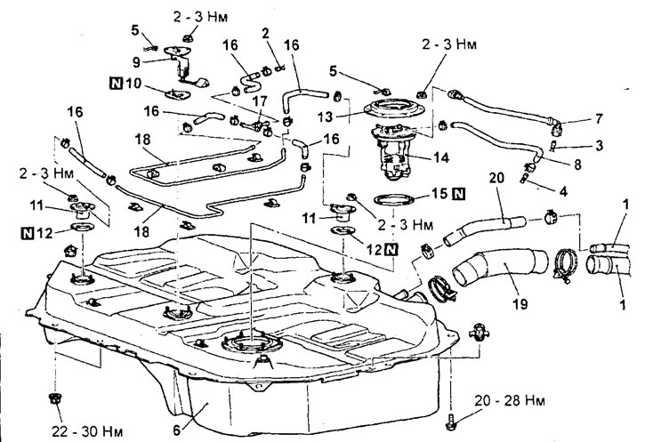
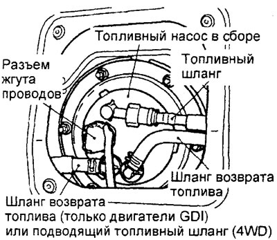
Removing the fuel tank (except 4WD models with 4G15 engine). 1 - connection of the drain pipe and the filler neck of the fuel tank, 2 - connection of the pipe of the fuel vapor recovery system, 3 - connection of the fuel pipe, 4 - connection of the fuel return pipe (Disconnect the left parking brake cable retainer, the right rear wheel speed sensor harness retainer, and the sensor harness connector), 5 - harness connector, 6 - fuel tank assembly, 7 - fuel hose, 8 - fuel return hose, 9 - fuel level sensor, 10 - gasket, 11 - fuel cutoff valve, 12 - gasket, 13 - cap, 14 - fuel pump assembly, 15 - gasket, 16 - evaporative emission system hose, 17 - check valve, 18 - evaporative emission system tube, 19 - fuel tank filler hose, 20 - drain hose.
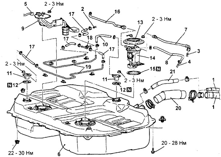
Removing the fuel tank (4WD models with 4G15 engine). 1 - connection of the drain pipe and the filler neck of the fuel tank, 2 - connection of the pipe of the fuel vapor recovery system, 3 - connection of the high pressure fuel pipe, 4 - connection of the fuel return pipe (Disconnect the left parking brake cable retainer, the right rear wheel speed sensor harness retainer, and the sensor harness connector), 5 - harness connector, 6 - fuel tank assembly, 7 - high pressure fuel hose, 8 - fuel return hose, 9 - fuel level sensor, 10 - evaporative emission system hose, 11 - fuel cutoff valve, 12 - gasket, 13 - cap, 14 - fuel pump assembly, 15 - gasket, 16 - fuel supply hose, 17 - evaporative emission system hose, 18 - check valve, 19 - evaporative emission system tube, 20 - fuel filler hose, 21 - drain hose.
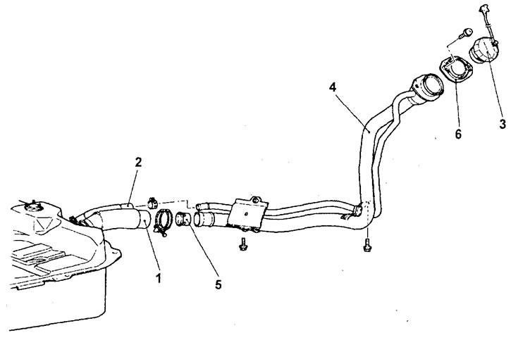
Removing the filler neck of the fuel tank.1 - filler hose connection, 2 - drain hose connection, 3 - fuel filler cap, 4 - fuel filler, 5 - fuel filler valve, 6 - seal.
When removing parts, pay attention to the following operations.
1. (4WD Models) Removing the fuel tank assembly.
A) Disconnect the flange of the drive gear of the final drive of the differential from the cardan shaft, and also unscrew the bolts of the differential mounting bracket.
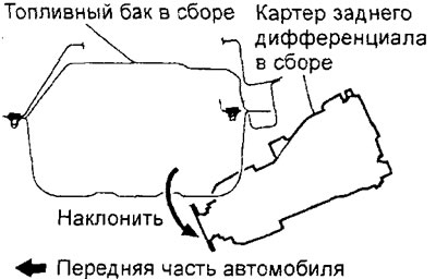
b) Remove the rear differential housing support bracket bolts and tilt the rear differential housing as shown.
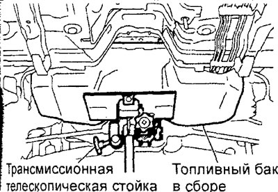
V) Support the fuel tank with the transmission telescopic stand and remove the fuel tank mounting bolts and nuts.
Attention: when performing this operation, do not allow the transmission telescopic rack to be disconnected from the fuel tank.
G) Tilt the fuel tank as shown in the illustration and disconnect all connectors from the fuel tank.
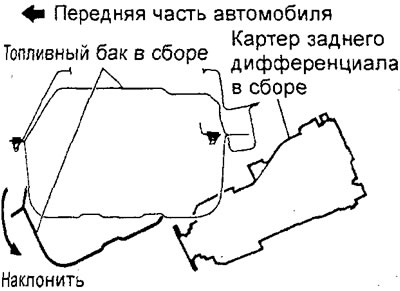
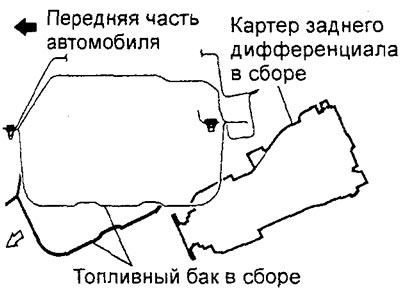
d) Remove the fuel tank assembly in the direction of the arrow in the figure.
Caution: When removing the fuel tank, do not hit it against the rear differential housing.
2. Removing the fuel pump assembly and fuel level sensor assembly.
Caution: Be careful not to damage the fuel pump assembly and fuel level sensor assembly from the fuel tank.
2. (2WD Models) Disconnecting the fuel tank harness connector.
Partially lower the fuel tank, then disconnect the harness connector.
Installation is made in an order, the return to removal.
When installing the parts, pay attention to the installation operation of the high pressure fuel hose and the fuel supply hose (only 4WD models with 4G15 engine).
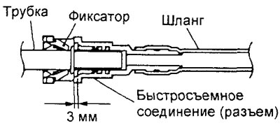
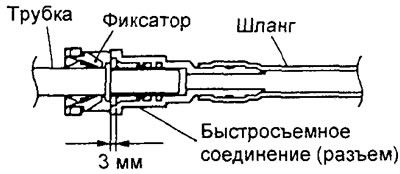
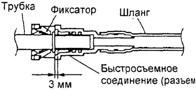
To connect the fuel hose, push the hose connector onto the tube until the connector retainer catches the lug of the tube. Then lightly pull the connector in the direction of disconnection to make sure the connection is secure. Check that the play in the connection does not exceed 3 mm.
After completing the installation of the parts, perform the following operations:
- A) (4WD Models) Install the cardan shaft.
- b) Install the center pipe of the exhaust system.
- V) Pour fuel into the tank.
- G) Check fuel line connections for leaks.
Examination
1. Check the condition of the fuel filler cap.
2. Check fuel hoses and tubes for cracks, kinks, deformation, fraying, or blockage. If there are signs of clogging or contamination of the fuel pipes located under the floor of the car, it is necessary to remove the corresponding section of pipes and blow it out with compressed air.
Attention: when replacing pipes, install only high-strength steel pipes, since copper and aluminum pipes cannot withstand the high pressure and vibrations that occur during vehicle operation.
3. Checking the fuel cut-off valve (on the fuel tank).
Note: A fuel cut-off valve is installed to prevent fuel from leaking out of the tank in the event of an accident (car flip) to the fuel vapor line.
A) Disconnect the EVAP hose and remove the fuel cutoff valve from the fuel tank.
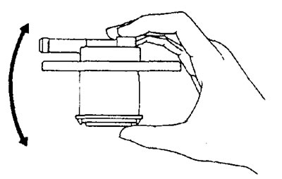
b) The valve is considered serviceable if, when the valve is slightly shaken up and down, the sound of the float moving inside is heard (knock).
V) Turn over and slowly submerge the fuel cut-off valve into a container of water, blocking the valve fitting with your finger as shown in the illustration.
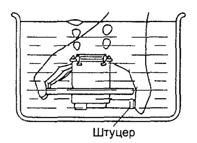
G) Check that there are no air bubbles that air has been removed from the valve, then slowly remove the valve from the container.
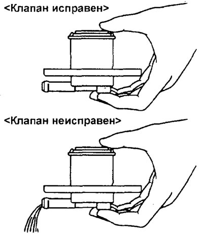
d) The valve is considered serviceable if after opening the fitting there is no water flowing out of the valve. In the event that water flows out through the fitting, the valve is considered faulty. If found to be faulty, replace: Fuel cut-off valve.
4. Checking the fuel tank.
A) Check the fuel tank for deformation, corrosion and cracks.
b) Check the fuel tank for dust or foreign particles inside.
Note: If the inside of the fuel tank needs to be cleaned, use kerosene, trichlorethylene, or a neutral detergent.
V) Check the in-tank pump fuel filter for damage or blockage.
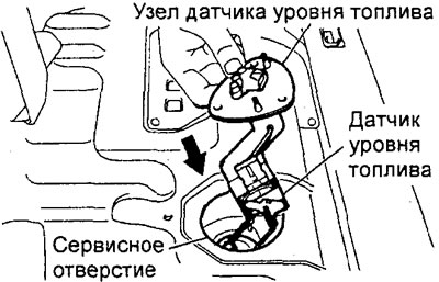
Fuel level sensor replacement
Note: On 4WD models with a 4G15 engine, the fuel level sensor is optional (the main one is located on the fuel pump).
1. Remove the rear seat cushion.
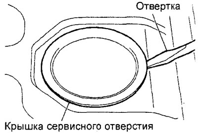
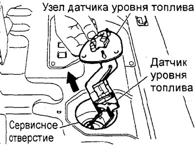
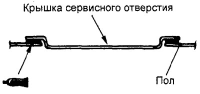
2. Remove the service port cover with a flat screwdriver (or similar tool), as it shown on the picture.
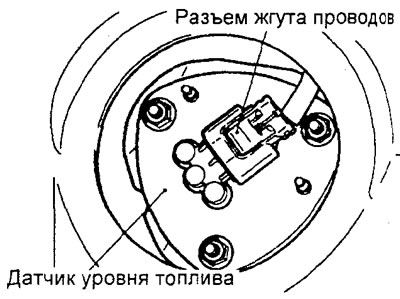
3. (Except 4WD models with 4G engine 15) Disconnect the wiring harness connector.
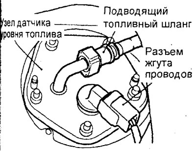
(4WD models with 4G15 engine) Disconnect the wiring harness connector and fuel supply hose.
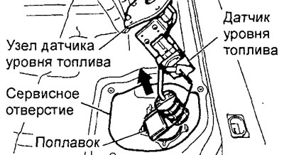
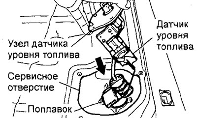
Unscrew the sensor mounting nuts and remove it from the fuel tank through the service hole.
Attention: be careful when removing and installing the sensor, do not damage the sensor float and the sensor itself.
Except 4G15-4WD.
4G15-4WD.
6. Install the fuel level sensor assembly through the service hole and tighten the fastening nuts to the specified torque.
Tightening torque - 2.5±0.5 N.m
Except 4G15-4WD.
4G15-4WD.
7. (Except 4WD models with 4G15 engine) Connect the wire harness connector.
8. (4WD models with 4G15 engine) Connect the wiring harness connector and fuel supply hose.
Attention:
- To connect the fuel hose, push the hose connector onto the tube until the connector retainer catches the lug of the tube. Then lightly pull the connector in the direction of disconnection to make sure the connection is secure.
- Check that the play in the connection does not exceed 3 mm.
9. Apply sealant to the contact surfaces of the service port cover and the floor panel, then install the cover.
Sealant Three bond 1521
10. Install the rear seat cushion.
Fuel pump replacement
1. Remove the rear seat cushion.
2. Remove the service port cover.
3. Disconnect the wiring harness connector and fuel hoses.
4. Turn away nuts of fastening, remove a cover and the fuel pump in gathering.
Attention: on 4WD models with 4G15 engine, be careful when removing the fuel pump assembly from the fuel tank, do not damage the fuel level sensor float (main) and the sensor itself.
5. Install the fuel pump assembly and cover, then tighten the fastening nuts to the specified torque.
Tightening torque 2 - 3 N.m
6. Connect fuel hoses and wiring harness connector.
Attention:
- To connect the fuel hose, push the hose connector onto the tube until the connector retainer catches the lug of the tube. Then lightly pull the connector in the direction of disconnection to make sure the connection is secure.
- Check that the play in the connection does not exceed 3 mm.
7. Install the service port cover.
8. Install the rear seat cushion.
Dismantling and assembly of the fuel pump
Removal of parts is carried out in the order of the numbers indicated in the figure "Disassembly of the fuel pump assembly".
Installation is made in an order, the return to removal.
When installing parts, pay attention to the installation operation of the sealing sleeve.
Apply a small amount of fuel to the grommet to prevent damage or twisting.
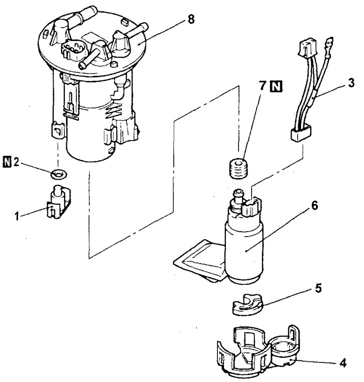
Disassembly of the fuel pump assembly (except 4WD models with 4G15 engine).1 - cover, 2 - O-ring, 3 - fuel pump harness, 4 - bracket, 5 - buffer, 6 - fuel pump, 7 - grommet, 8 - fuel filter assembly.
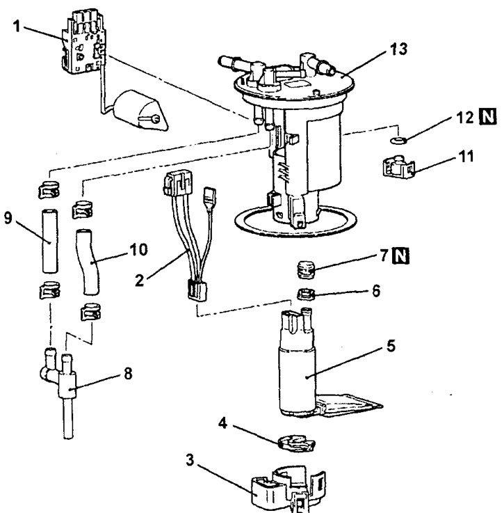
Disassembly of the fuel pump assembly (4WD models with 4G15 engine). 1 - fuel level sensor (basic), 2 - fuel pump harness, 3 - bracket, 4 - buffer, 5 - fuel pump, 6 - spacer, 7 - grommet, 8 - priming pump, 9 - fuel hose (suction), 10 - fuel hose (returnable), 11 - cover, 12 - O-ring, 13 - fuel filter assembly.