
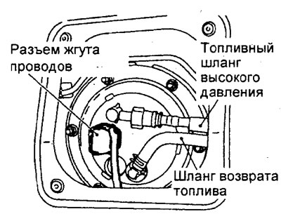
Bleeding residual pressure from the high pressure fuel line
Note: since the fuel line is under pressure, before removing the components of the fuel system (hoses, pipes, etc.) perform this operation to reduce the fuel pressure and prevent it from splashing.
1. Remove the rear seat cushion.
2. Remove the service port cover.
3. Disconnect the fuel pump harness connector.
4. Start the engine and let it run until it runs out of fuel. After the engine stalls on its own, turn the ignition key to the "OFF" (OFF).
5. Connect the fuel pump harness connector.
6. Install the service hole cover, then install the rear seat cushion.
Checking the operation of the fuel pump
1. Check the operation of the fuel pump by forcibly turning it on with a tester.
2. If the fuel pump does not work, then perform the specified check, if the pump is working, then check the power supply circuit of the pump.
A) Switch off the ignition.
b) Remove the rear seat cushion
V) Remove the service port cover.
G) Disconnect the fuel pump harness connector.
d) Connect the wires from the battery to the coca connector as shown.
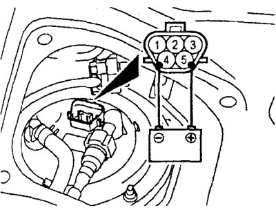
e) Check if you can hear the sound of the pump running.
Note: Since the pump is installed in the fuel tank, remove the fuel tank filler cap for better audibility.
and) If no sound is heard from the pump, replace the pump.
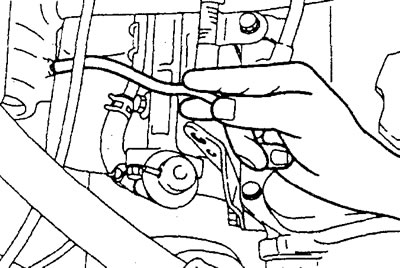
h) Check for fuel pressure by lightly pinching the high pressure fuel hose with your fingers.
And) Connect the fuel pump harness connector.
To) Install the service port cover. Then install the rear seat cushion in place (if filmed).
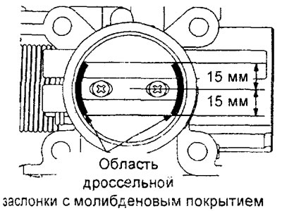
Cleaning the throttle body
1. Start the engine, warm it up to a coolant temperature of 80°C or higher, and then stop the engine.
2. Disconnect the intake air hose from the throttle body.
3. Apply washing cleaner to the fabric.
Cleaner - Three bond 6601
4. Use this cloth to clean the surface of the throttle body.
Attention:
- Do not allow the cleaner to get directly onto the damper.
- Do not allow the cleaner to enter the spare channel (to idle speed control servo), as well as to the throttle position sensor through the axle.
- Do not wash off the molybdenum coating applied near the throttle shaft.
5. Connect the air inlet hose to the throttle body.
6. Adjust base idle speed (see related section).
Adjusting the Factory Adjustment Screw
Note:
- - Do not, unless absolutely necessary, touch the
factory adjustment screw on the throttle body, which has been precisely adjusted at the factory. - - In case the
screw is out of factory adjustment by mistake, adjust it according to the procedure below.
1. Loosen the accelerator pedal cable.
2. Loosen the locknut of the factory adjustment screw
3. Turn the factory adjustment screw «Fixed SAS» counterclockwise until the throttle is fully closed.
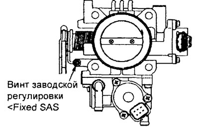
4. Screw in the factory adjustment screw «Fixed SAS» before touching the throttle lever (before throttle opening). From this position, turn the screw 1 more turn.
5. Holding the factory adjustment screw «Fixed SAS» from turning, securely tighten the locknut.
6. Adjust the accelerator pedal cable.
7. Adjust the base idle speed.
8. Verify that the throttle position sensor output voltage is correct.
Base idle speed adjustment
Attention:
- - The base idle speed is set at the factory with the idle speed screw (SAS). During operation, additional adjustment is usually not required.
- - If by mistake the factory setting was violated (SAS screw position changed), then the idling speed may become either too high or too low when the additional load on the engine is turned on (e.g. when the air conditioning compressor is turned on).
- If adjustment is still necessary, then before starting work, check the spark plugs, injectors, idle speed control servo, compression, etc.
1. Before starting the inspection and adjustment procedures, prepare the vehicle in accordance with the following points.
A) Coolant temperature should be 80-95°C.
b) Lighting, electric fan and all additional equipment must be turned off.
V) Set the CVT or automatic transmission selector lever to position "R".
G) Set the steering wheel to the straight ahead position.
2. Connect the tester to the diagnostic socket (when the ignition key is in position "OFF" (OFF)).
Note: When the tester is connected, the control pin of the diagnostic socket is connected to "weight".
3. Start the engine and let it idle.
4. If the test is carried out using a tester, then select item No. 30 of the function "ACTUATOR TEST" tester (set the idle speed control servo to the base speed position).
5. Measure the engine speed at idle.
Rated value - 700±50 rpm
Note:
- - On a new car (with a mileage of not more than 500 km) idle speed may be 20-100 rpm less than nominal, but adjustment is not required in this case.
- - If on a car with a mileage of more than 500 km, the engine stalls or the idle speed is too low, then foreign particles have probably been deposited inside the throttle body (cleaning needed).
6. If the base idle speed differs from the nominal value, then adjust it by turning the idle speed adjustment screw (SAS).
Engine 4G15.
Engine 4G93.
7. Press the button "Clear" tester to complete the function "ACTUATOR TEST" tester (remove the idle speed control servo from the forced control mode).
Attention: if the function "ACTUATOR TEST" tester is not completed, the forced control mode of the device will be maintained for 27 minutes.
8. Turn off the ignition.
9. Disconnect a tester from a diagnostic socket.
10. Start the engine again and let it idle for about 10 minutes. Check that the idle speed is within the nominal value.
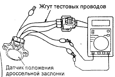
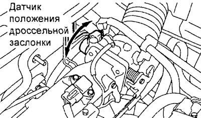
Throttle position sensor adjustment
1. Connect the tester to the diagnostic socket (ignition off).
2. If the tester is not available, then perform the following operations.
A) Disconnect the throttle position sensor connector.
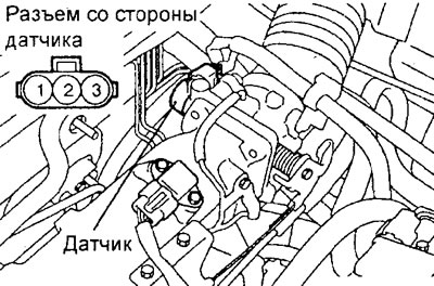
Engine 4G15.
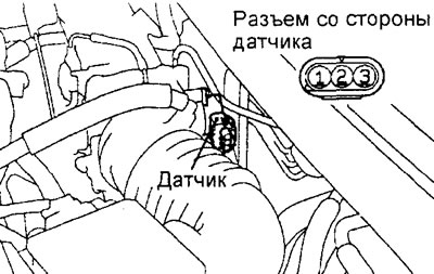
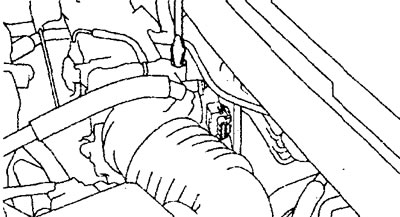
Engine 4G93.
b) Connect the test lead harness between the sensor side connector and the harness side sensor connector.
V) Connect a digital voltmeter between the terminal "3" (sensor signal: yellow test harness clamp) and conclusion "1" ("weight" sensor: red test harness clamp) throttle position sensor connector.
3. Turn the ignition key to position "ON" (ON) (do not start the engine).
4. Check the throttle position sensor output voltage.
Rated value - 0.335 - 0.935 V
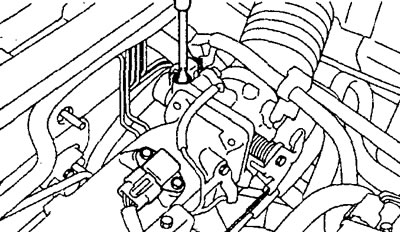
5. If the output voltage does not correspond to the nominal value, then loosen the screws securing the throttle position sensor and, by turning the sensor housing, adjust its position so that the sensor output voltage corresponds to the nominal value. After that, securely tighten the throttle position sensor mounting screws in this position.
Engine 4G15.
6. Turn the ignition key to position "OFF" (OFF).
7. Disconnect the tester. If the tester is not being used, disconnect the test harness and connect the throttle position sensor connector.
8. If a diagnostic trouble code is displayed after turning on the ignition, then remove it with a tester or by disconnecting the wire from the negative terminal of the battery for at least 10 seconds. Reconnect the cable to the negative battery terminal, start the engine and let it idle for at least 10 minutes.
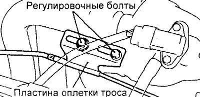
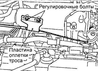
Accelerator pedal cable adjustment
1. Check the accelerator pedal cable sheath for damage, make sure there are no sharp bends in the cable.
2. Adjust the free play of the accelerator pedal cable when the accelerator pedal is released.
Nominal value - 1-2 mm
3. If the free play of the accelerator pedal does not correspond to the nominal value or there is no free play, then adjust it.
A) Loosen the cable adjusting bolts on the intake manifold.
Engine 4G15.
Engine 4G93.
b) By moving the cable sheath plate, set the free play of the cable according to the nominal value.
V) Tighten the cable adjusting bolts to the specified torque.
Tightening torque - 4 - 6 Nm
Fuel pressure check
1. Bleed residual fuel pressure from the high pressure fuel lines (see relevant subsection).
2. Installation of a manometer or pressure sensors before taking measurements (from the side of the high pressure fuel supply hose).
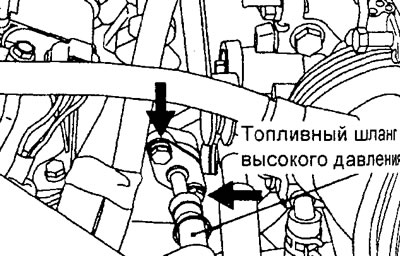
A) Disconnect the high pressure fuel slag from the fuel manifold.
Caution: due to residual pressure in the high pressure fuel line, cover the rag joint between the hose and the fuel manifold to prevent fuel splashing.
b) Prepare adapter (tee) for connection to the fuel manifold.
V) Connect the adapter between the high pressure fuel hose and the fuel manifold.
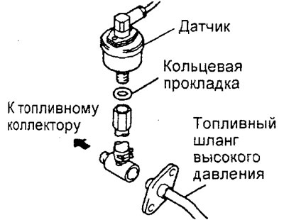
G) Install a pressure gauge or pressure transducer on the adapter. When doing this, be sure to install suitable O-rings to prevent fuel leaks.
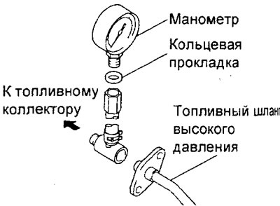
Checking the pressure with a pressure gauge.
Checking the pressure with a pressure gauge.
d) (Checking with a pressure transducer) Connect the power wire of the pressure sensor to the power supply (cigarette lighter), and the signal wire to the tester.
3. Check for leaks after installing the pressure gauge.
A) Connect the tester to the diagnostic socket.
b) Turn on the ignition. Do not start the engine.
V) Select sub-item No. 07 of item "ACTUATOR TEST" tester and activate the fuel pump. Make sure that there are no fuel leaks at the connections between the pressure gauge and the elements of the special tool.
G) Stop the fuel pump using a tester or turn the ignition key to the "LOCK" or "OFF".
4. Measuring fuel pressure while the engine is running at base idle speed.
A) Start the engine and let it run at idle.
b) Measure the fuel pressure while the engine is idling.
Rated value (at base idle speed) - approx. 265 kPa
5. Measuring fuel pressure with fuel pressure regulator hose disconnected.
A) Disconnect the vacuum hose from the fuel pressure regulator and close it with your finger.
Engine 4G15.
Engine 4G93.
b) Measure fuel pressure.
Rated value (at base idle speed) — 324-334 kPa
V) Check that the fuel pressure at idle does not drop, even after several depresses of the accelerator pedal.
G) While pressing the accelerator pedal several times in a row, lightly pinch the fuel return hose with your fingers. Check that fuel pressure is felt in the hose.
Note: If the fuel flow is low, no pressure will be felt in the fuel return hose.
6. Evaluation of the results of measuring fuel pressure with the fuel pump turned on.
If any of the results of the check in the previous paragraph does not correspond to the norm, then troubleshoot and eliminate them in accordance with the table "Checking the fuel pressure with the pump on".
Table. Checking the fuel pressure with the pump on.

7. Checking the drop in fuel pressure after turning off the fuel pump.
A) Stop the engine (turn off the fuel pump) and check for changes in the pressure gauge or fuel pressure gauge. The fuel system is OK if the pressure in the fuel line does not decrease within 2 minutes. If the pressure drops, then determine the rate of pressure drop (gradually/instantly) and troubleshoot and correct them.
b) If the fuel pressure drops gradually after stopping the engine, then either the injector is leaking or there are leaks through the fuel pressure regulator valve (loose valve seat). Replace defective element.
V) If, after stopping the engine, the fuel pressure drops immediately, the check valve in the fuel pump remains open. Replace fuel pump.
8. Removal of the manometer or pressure sensor after completion of measurements.
A) Release residual pressure from the high pressure fuel line.
b) Disconnect the special tool assembly with pressure gauge or pressure sensor from the fuel manifold.
Caution: due to residual pressure in the high pressure fuel line, cover the junction of the special tool with the fuel manifold with a rag to prevent fuel splashing.
V) Disconnect the high pressure fuel hose from the special tool.
G) Replace the O-ring on the high pressure hose tube flange with a new one.
Note: Apply engine oil to the new O-ring before installing.
d) Install the high pressure fuel hose tube flange into the fuel rail and tighten the flange mounting bolts to the specified torque.
Tightening torque - 7-11 Nm
9. Check for fuel leaks after removing the pressure gauge or pressure sensor.
A) Connect the tester to the diagnostic socket.
b) Turn on the ignition. Do not start the engine.
V) Select sub-item No. 07 of item "ACTUATOR TEST" tester and activate the fuel pump. Check for fuel leaks.
G) Stop the fuel pump.
d) Switch off the ignition and disconnect the tester.