



Contents: Checking the condition and tension…⤓ Checking for damage to high-voltage…⤓ Checking the air supply pipe ⤓ Checking the oil line hose to the…⤓ Checking the crankcase ventilation…⤓ Checking the ventilation hose of the…⤓ Checking the Positive Crankcase…⤓ Checking the PCV valve ⤓ Replacing spark plugs ⤓ Checking radiator hoses for damage…⤓ Checking the coolant level in the…⤓ Replacing the coolant in the engine…⤓ Draining the coolant from the…⤓ Checking the air filter for…⤓ Replacing the air filter ⤓ Checking the electrolyte level in…⤓ Replacing the fuel filter ⤓ Checking for leaks in the exhaust…⤓ Replacing the cabin filter ⤓
Checking the condition and tension of the auxiliary equipment drive belt
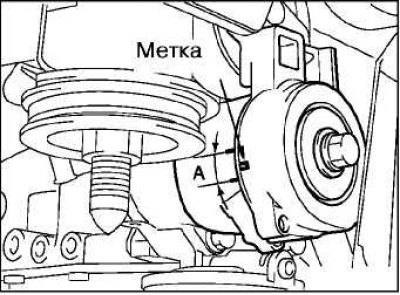
Check the belt along its entire length for cracks, delamination and wear.
Make sure that the mark is in the area marked A when installing.
Caution! Check the belt after turning the engine crankshaft clockwise for at least one revolution.
If the mark does not fall within the specified area, replace the drive belt.
Note: There is no need to check the accessory drive belt if the tensioner is installed.
Checking for damage to high-voltage wires
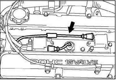
Check the high-voltage wires and spark plug tips for damage, weakening of the contact pressure, and also check that they are installed correctly.
Check for contamination on the contacts of high-voltage wires, spark plugs and ignition coils, etc.
If there is contamination, clean it; if the elements are damaged, replace them.
Checking the air supply pipe
Dirt and dust that gets on the air filter can clog the filter and reduce engine power.
Check the air supply pipe for cracks or damage.
Checking the oil line hose to the turbocharger
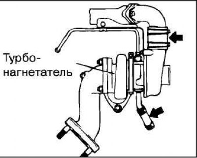
An oil leak from the turbocharger oil supply hose may result in insufficient lubrication of this unit, which will result in a decrease in engine power.
Check the turbocharger oil supply hose for cracks or damage.
Checking the crankcase ventilation breather hose
Check the breather hose for cracks or damage.
Clean the inside of the breather hose if necessary.
Check if the positive crankcase ventilation filter is clogged.
Checking the ventilation hose of the positive crankcase ventilation system
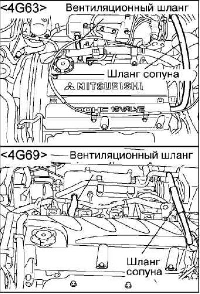
Check the hose along its entire length, using a mirror if necessary.
Check that the fasteners are securely fastened and that there are no leaks in the connections.
Hoses must be replaced immediately if there are signs of deterioration or damage.
Checking the Positive Crankcase Ventilation (PCV) System
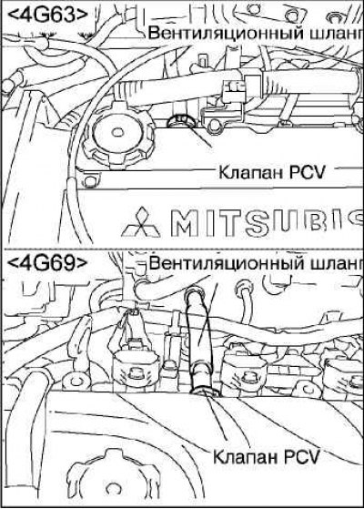
Remove the vent hose from the PCV valve.
Remove the PCV valve from the cylinder head cover.
Install the PCV valve and vent hose.
Start the engine and let it idle.
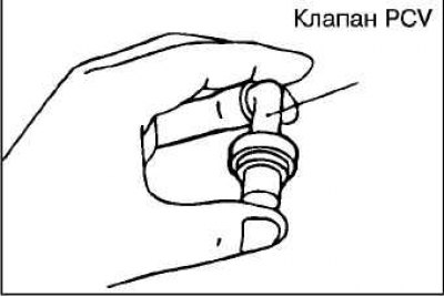
Place your finger directly over the PCV valve opening and check to see if you can feel the vacuum being created in the intake manifold.
At the same time, the plunger in the PCV valve begins to move alternately back and forth.
If there is no vacuum felt, replace the PCV valve.
Checking the PCV valve
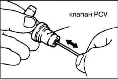
Insert a thin rod into the PCV valve from the side shown in the figure (the cylinder head cover side) and move it back and forth to check the plunger mobility.
If the plunger does not move, the PCV valve is clogged. The valve needs to be cleaned or replaced.
Replacing spark plugs
After removing the old spark plugs, install new ones in their place and tighten them to the recommended tightening torque.
Checking radiator hoses for damage and secure connections
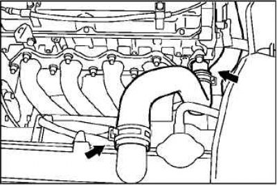
Check the hose along its entire length, using a mirror if necessary.
Check that the hoses pass through the centers of the gaskets.
Check that the fasteners are securely fastened and that there are no leaks in the connections.
Checking the coolant level in the expansion tank
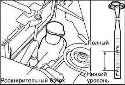
Check that the coolant level is between the "MAX" and "MIN" marks on the expansion tank at normal engine operating temperature.
Replacing the coolant in the engine cooling system
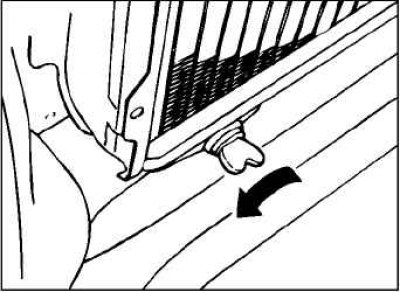
Stop the engine after it has warmed up completely.
Add a cleaning additive to the coolant to flush the cooling system and start the engine.
Loosen the drain plug, remove the radiator cap and drain the coolant.
Flush the cooling system by pouring clean water through the radiator neck.
Replace the drain plug after flushing is complete.
Drain the coolant from the expansion tank.
Install the expansion tank.
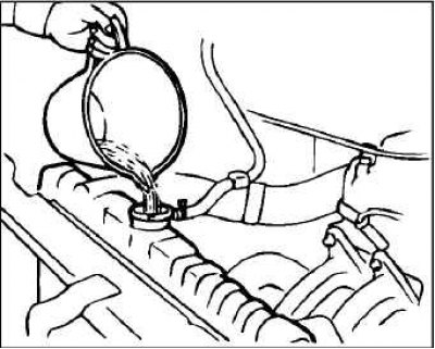
Depending on the expected operating conditions, determine how much long-life coolant, antifreeze, or corrosion inhibitor must be added to obtain the proper coolant. Recommended antifreeze: DIA QUEEN SUPER LONG LIFE COOLANT or equivalent.
Warning! Do not use alcohol-based antifreeze (including methanol) or various coolants mixed with alcohol-based antifreeze. Using the wrong antifreeze may cause corrosion of aluminum components.
Fill the cooling system with distilled water through the filler neck, if necessary, add the appropriate amount of long-life antifreeze.
Fill the expansion tank with coolant.
Install the radiator and expansion tank caps.
After road testing, check the coolant level.
Caution! When removing the radiator cap, be careful, steam or hot liquid may escape from underneath it.
Draining the coolant from the cylinder block through the drain plug
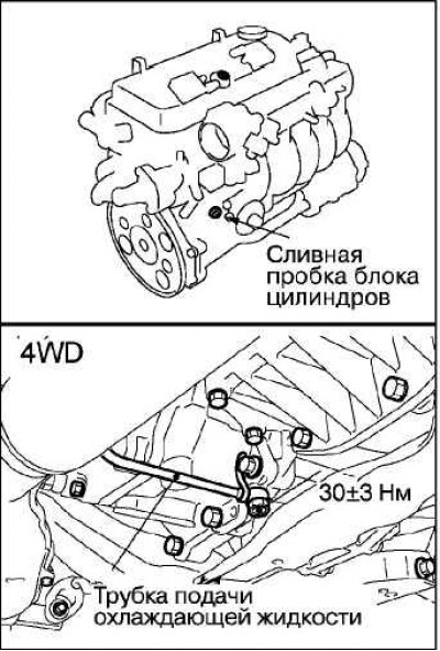
Drain the coolant from the cylinder block by unscrewing the plug on the block and then removing the radiator cap.
Drain the coolant from the cylinder block by unscrewing the drain plug.
On all-wheel drive models, drain the coolant through the coolant supply pipe to the transfer case.
Remove the expansion tank and drain the remaining coolant.
After draining the coolant, flush the cooling system with water by pouring it through the radiator neck.
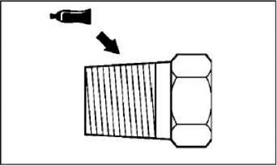
Coat the threaded portion of the drain plug with the recommended sealant and tighten it to the recommended tightening torque.
Recommended sealant: ЗМ Nut Locking Part # 4171 or equivalent
Tightening torque: 44 ±5 Nm.
Replace the radiator cap.
Install the expansion tank.
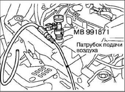
Select the appropriate concentration of coolant within the range of 30 to 60% depending on the operating temperature. Use the appropriate special tool to fill the coolant (MB991871). A solution of 50% distilled water and 50% antifreeze (freezing point -31°C) is usually used.
Note: For instructions on using the special tool MB991871 to fill the coolant, refer to the Repair Manual.
Recommended antifreeze: DIA QUEEN SUPER LONG LIFE COOLANT or its equivalent.
Filling volume: 7.0 l.
Warning! Do not use alcohol-based antifreezes (including methanol) or various coolants mixed with alcohol-based antifreezes. Using the wrong antifreeze may cause corrosion of aluminum components.
Install the radiator cap.
Start the engine and warm it up until the thermostat opens.
Touch the radiator hose with your hand to check for circulation of hot coolant.
After the thermostat opens, press the gas pedal several times to briefly increase the engine speed, then turn it off.
Let the engine cool down and add coolant to the expansion tank up to the "MAX" mark.
If the coolant level has dropped excessively, repeat the operations starting with starting and warming up the engine.
Checking the air filter for blockages or damage
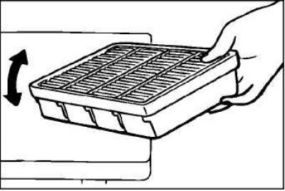
Check the air filter for clogging or damage.
Clean the accumulated dust from the filter as follows.
Tap the filter lightly on the edge of the workbench.
Blow out from the inside with compressed air.
Clean the filter cover from dust.
Install the filter housing.
Replacing the air filter
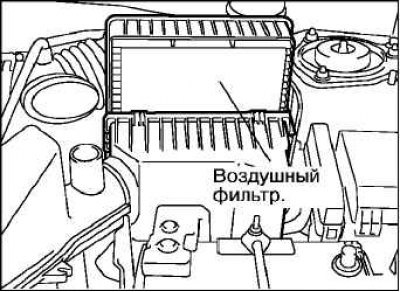
As the air filter becomes contaminated with dust during operation, its filtering capacity decreases significantly. Replace the air filter.
Unfasten the filter cover retainer.
Replace the filter element with a new one.
Make sure to completely close the filter element cover before fastening the latch.
Checking the electrolyte level in the battery
Check if the electrolyte level is between the upper and lower level marks.
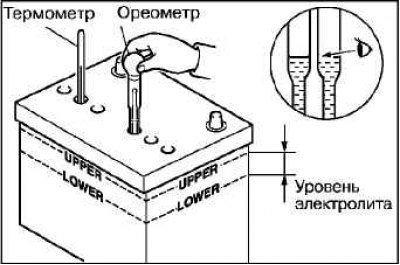
Warning! If the electrolyte level is below the lower level mark, the battery may explode during operation.
Caution: If the electrolyte level is above the upper level mark, electrolyte leakage may occur.
Use a thermometer and a hydrometer to check the specific gravity of the electrolyte.
Standard value: 1.220–1.290 (20°C).
The density of the electrolyte changes with temperature, so to bring the density values to a certain temperature, use the formula below. To determine the permissibility of a given electrolyte density, use the calculated value.
D20 = (t 20) x 0,0007 + Dt.
D20 – electrolyte density reduced to a temperature of 20°C.
Dt – readings of the oreometer.
t – thermometer readings.
Replacing the fuel filter
Remove the rear seat cushion assembly.
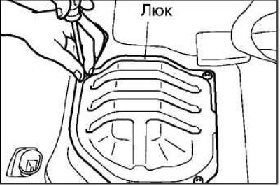
Remove the hatch cover.
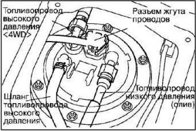
Disconnect the connector, hose and tube.
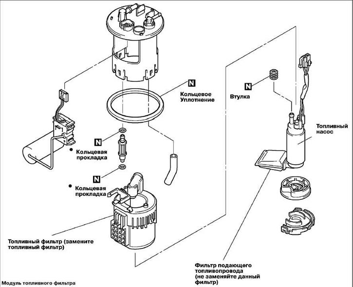
Loosen the nuts and remove the fuel pump module.
Remove the fuel filter from the fuel pump.
Install a new fuel filter.
Caution: To avoid damaging the bushing and O-ring, apply unleaded gasoline to them immediately before installation.
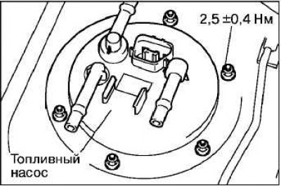
Install the fuel pump module.
Tighten the mounting nuts to the recommended torque.
Recommended tightening torque: 2.5±0.4 Nm.
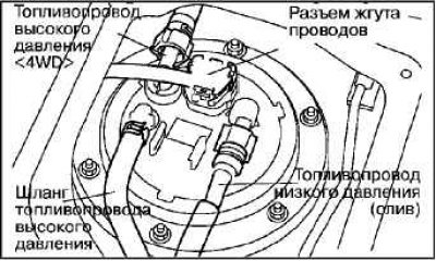 |  |
Connect the connector, hose and tube.
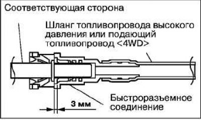
Caution! After connecting the high pressure hose or fuel supply line (4WD), pull it slightly to make sure it is securely installed. Also make sure there is approximately 3 mm of free play.
Install the hatch cover.
Install the rear seat cushion.
Checking for leaks in the exhaust system and correct installation of its components
Make sure that the exhaust system does not come into contact with body components.
Check that the exhaust system components are not damaged by stones, etc.
Start the engine and check the exhaust system for leaks.
Replacing the cabin filter
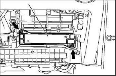
Remove the glove box.
Remove the two indicated screws and replace the cabin filter.
Install the glove box.