
Engine oil change
Start the engine and let it warm up to operating temperature (80–90°C).
Stop the engine, remove the oil filler cap.
Remove the drain plug from the engine oil pan and drain the engine oil.
Attention! When performing this operation, be careful, the engine oil is hot.
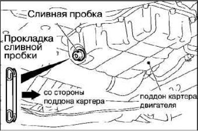
Replace the drain plug gasket with a new one so that it is oriented as shown in the illustration and tighten the plug to the recommended torque.
Recommended tightening torque: 39±5 Nm.
 |  |
Fill with the recommended amount of engine oil.
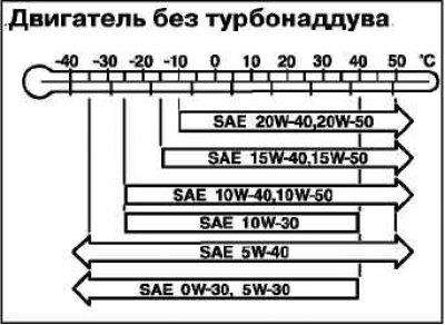
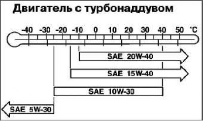
Recommended engine oil
Classification by ACEA and API: «ACEA A1, A2, A3».
Quality class SG or higher.
Overall volume (including oil filter volume)
4.3 l - 4G63 (N/A, 4G69 A/T).
4.6 l - 4G63 (T/C, 4G69 M/T).
Remove the dipstick and check if the engine oil is between the marks «MAX» And «MIN».
Reinstall the oil filler cap.
Start the engine and let it idle for a few minutes.
Stop the engine and check the engine oil level.
Oil filter replacement
Start the engine and let it warm up to operating temperature (80–90°C).
Stop the engine, remove the oil filler cap.
Remove the drain plug from the engine oil pan and drain the engine oil.
Attention! Be careful when performing this operation, as hot oil.
Remove the engine compartment cover.
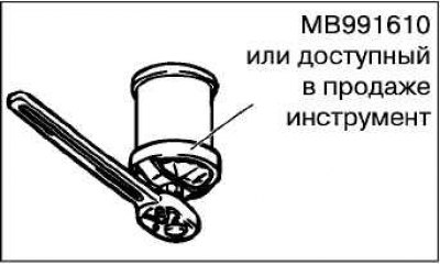
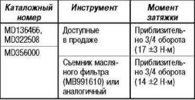
Using the tool indicated in the table below, remove the oil filter.
Clean the mating surface of the oil filter.
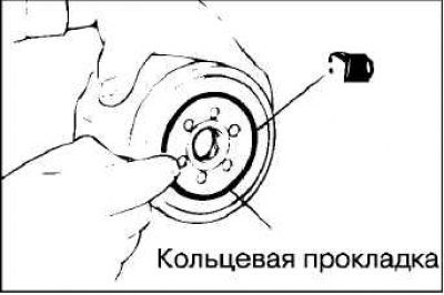
Apply a small amount of engine oil to the O-ring of the new oil filter.
Install the new oil filter until the O-ring touches the mating surface and tighten the filter with the appropriate special tool to the recommended tightening torque.
Install a new drain plug and fill with the correct amount of engine oil.
Start the engine.
Increase the engine speed 2-3 times and check that there are no leaks along the filter mating surface.
Engine idle speed check
Note. Before carrying out the check, bring the car into a condition for carrying out control and diagnostic operations.
Turn the ignition key to position «LOCK» («OFF»).
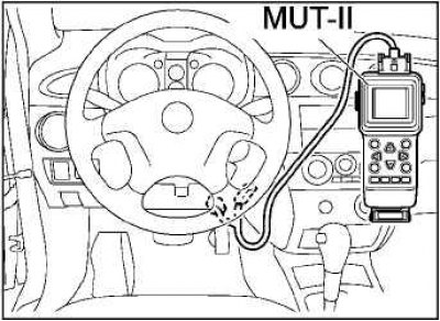
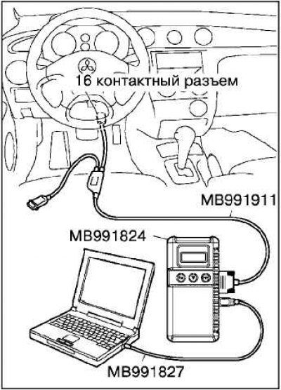
Connect to diagnostic socket MUT-II/III.
Connect a stroboscope.
Start the engine and let it idle.
Check that the ignition timing is set to the recommended value.
Recommended value:
- about 10°to TDC - 4G63 N / A, 4G69;
- about 5°to TDC - 4G63 T / C.
Check idle speed.
Recommended value: 750±100 min-1 – 4G69 A/T, 4G63; 680±100 min-1 – 4G69 M/T.
Note. The idle speed is controlled automatically.
Note. If the idle speed is not within the recommended value, perform an MPI system check.
Turn the ignition key to position «LOCK» («OFF») and disconnect the MUT-II/III.
Checking the concentration of CO in the exhaust gases
Note. Before carrying out the check, bring the car into a condition for carrying out control and diagnostic operations.
Turn the ignition key to position «LOCK» («OFF»).
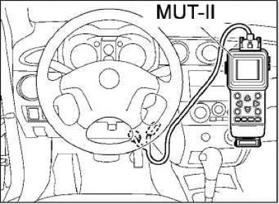 | 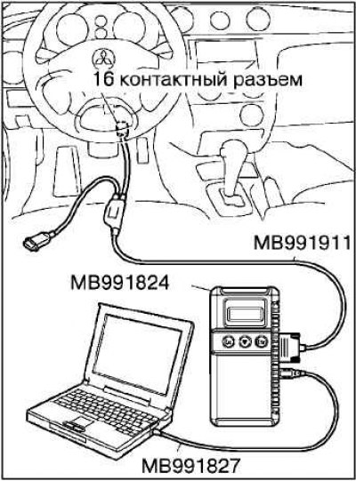 |
Connect to diagnostic socket MUT-II/III.
Connect a stroboscope.
Start the engine and let it idle.
Check that the ignition timing is set to the recommended value.
Recommended value:
- about 10°to TDC - 4G63 N / A, 4G69;
- about 5°to TDC - 4G63 T / C.
Set the engine speed to 2500 min for 2 min-1.
Turn on the device for measuring CO and CH in the exhaust gases.
Measure the concentration of CO and CH in the exhaust gases.
Recommended values
CO concentration: no more than 0.5%.
CH concentration: no more than 100 ppm.
If the concentration differs from the recommended values, then the following points should be checked:
- diagnostic output;
- fuel pressure;
- nozzles;
- ignition coils, spark plugs, high voltage wires;
- EGR system;
- fuel vapor recovery system;
- compression.
Note. If the concentration of CO and CH in the exhaust gases is higher than the recommended values, even if all check points are positive, replace the three-way catalytic converter.
Turn the ignition key to position «LOCK» («OFF»), and disconnect the MUT-II/III.
Checking the performance of the exhaust gas recirculation system (EGR)
Remove the EGR valve and inspect it for valve sticking, carbon deposits, etc. If there are any defects, flush the valve in an appropriate solvent to clean it and ensure proper operation.

Connect a vacuum pump to the valve.
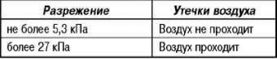
Create a vacuum of 67 kPa and check the tightness of the valve.
Check if air is passing through the EGR system air passage or not.
Replace gasket and tighten to recommended torque. Recommended tightening torque: 20±2 Nm.
Checking the solenoid valve of the EGR system
Disconnect the vacuum hose from the solenoid valve.
Disconnect the wiring harness.
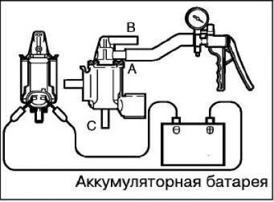
Connect the vacuum pump to port A of the solenoid valve.
Check for leaks by applying a vacuum with voltage applied directly from the battery to the EGR solenoid valve and without voltage applied.

Measure the resistance between the terminals of the solenoid valve.
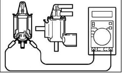
Recommended value: 29-35 ohms (at 20°C).
Remove the EGR valve and inspect it for valve sticking, carbon deposits, etc. If there are any defects, flush the valve in an appropriate solvent to clean it and ensure proper operation.
EGR valve check (stepper motor; check the valve by the sound of operation)
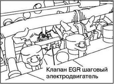
Check for a sound coming from the stepper motor that should be heard when the ignition is turned on (the engine does not start).
If the operation sound of the stepper motor is not heard under the above conditions, check the condition of the stepper motor power supply circuit.
Note. If the power circuit is working, then the cause of the malfunction may be in the stepper motor itself or in the electronic engine control unit.
Coil Resistance Test
Disconnect the connector from the EGR valve.
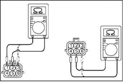
Measure the resistance of the valve coil between terminals 2 and 1 or 3 of its connector.
Rated value: 20-24 ohms (at 20°C).
Measure the resistance of the valve coil at terminals 5 and 6 or 4 of its connector.
Rated value: 20-24 ohms (at 20°C).
Install a new EGR valve, replacing the gasket, and tighten the sensor mounting bolts to the recommended torque.
Recommended tightening torque: 24±4 Nm.
Checking the function of the valve
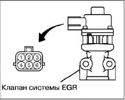
Remove the EGR valve.
Connect Special Tool (test lead harness MB991658) to the terminals of the valve connector itself.
Connect pin 2 to terminal (+) battery.
Attention! Continued connection of the valve to the power supply may damage the coil.
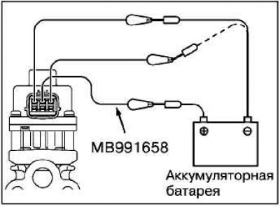
Connect pins 1 and 3 to terminal (–) battery. If the stepper motor is working, a slight vibration will go through its body.
Connect Lead (+) battery to terminal 5 of the sensor.
Attention! Continued connection of the valve to the power supply may damage the coil.
Connect pins 4 and 6 to terminal (–) battery.
If the stepper motor is working, a slight vibration will go through its body.
Install a new EGR valve, replacing the gasket, and tighten the sensor mounting bolts to the recommended torque.
Recommended tightening torque: 24±3 Nm.
Checking for carbon deposits
Remove the EGR valve and check for carbon deposits in the gas passages of the EGR valve. If there are heavy deposits, remove them with a wire brush.
Attention! The use of liquid solvents when removing carbon deposits is not allowed: the solvent, getting on the motor windings, causes its failure.
Install a new EGR valve, replacing the gasket and tighten the sensor mounting bolts to the recommended torque.
Recommended tightening torque: 24±4 Nm.