
Removing
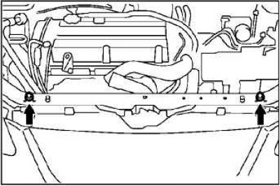
Remove the lower protective covers.
Raise the power unit to release the engine mount from the load on the power unit and remove the engine mount.
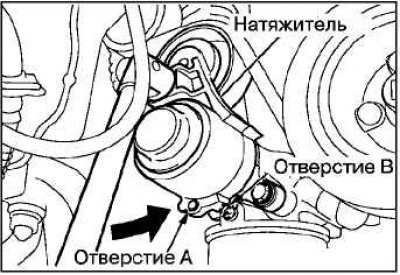
Insert special tool (wrench or ratchet with 12.7 mm insert) into a special hole in the automatic tensioner of the accessory drive belt assembly.
Turn the auto tensioner counterclockwise to align the hole «A» with hole «IN».
Attention! If the accessory drive belt is reused, chalk on the reverse (non-working) side of the belt with an arrow indicating the direction of rotation.
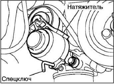
Insert a special key into the hole for fixing the automatic tensioner and remove the accessory drive belt.
Note. Instead of a special key, it is allowed to use a wire that must be bent at a right angle.
Remove residual pressure from the high pressure fuel line.
Drain the coolant.
Drain the engine oil.
Drain the oil from the gearbox and transfer case (4WD models).
Remove the hood.
Remove the air filter.
On 4G69 series engines, disconnect the accelerator pedal cable.
Remove the radiator assembly.
Disconnect the exhaust pipe from the exhaust manifold.
Remove the gearbox and transfer case assembly.
Remove the accessory drive belt.
Remove the power steering pump from the engine along with the hoses and bracket connected to it.
Note. Secure the power steering pump and hoses with wire in a location where it will not be damaged or interfere with the removal and installation of the engine assembly.
Disconnect the compressor and A/C magnetic clutch wire connector assembly.
Remove the compressor from its bracket along with the connected hoses.
Note. Mount the A/C compressor pump assembly with hoses to the body in a location where it will not be damaged or interfere with the removal and installation of the engine assembly.
On 4G69 series engines, disconnect the high pressure fuel hose.
Removing the gearbox assembly
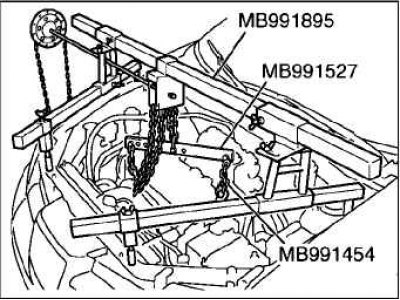
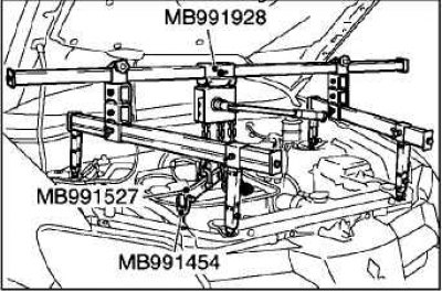
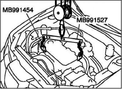
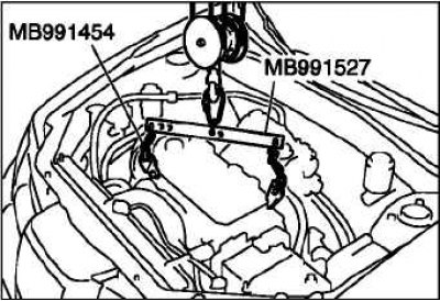
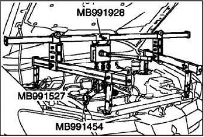
Temporarily install 2 bolts in the upper radiator supports to install the special tools as shown.
Remove the transmission assembly.
Install a hydraulic wheel jack under the engine.
Remove the special tools used to remove the gearbox.
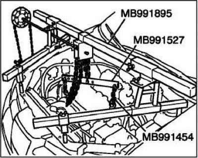
Fasten the engine to the yoke and hang it on a hoist or similar device as shown in the figure.
Insert a piece of wood between the jack foot and the engine oil pan.
Raise the engine slightly to relieve the support from the weight of the engine.
Loosen the nuts and bolts of the bracket and remove the engine support assembly with the bracket.
Check that all cables, wires, hoses and other connections are disconnected from the engine.
Install special tools on the engine (engine lift and traverse).
Using these tools, lift the engine assembly up out of the engine compartment.
Note. Make sure that it does not move to the side and does not sway.
Installation
Installation is made in an order, the return to removal.
With the help of special devices (engine lift and traverse) lower and install the engine assembly in the engine compartment.
Remove the special tools from the engine (engine lift and traverse).
When installing the engine, check that the wires, tubes, hoses, and wire connectors are connected correctly. Make sure they are not twisted or damaged.
Check that the clamps and clamps are installed correctly.
Place a hydraulic wheel jack under the engine.
Insert a piece of wood between the jack foot and the engine oil pan. Establish an engine support, adjusting its position by means of a jack.
While supporting the engine with a jack, disconnect the hoist.
 |  |
When installing the self-locking nut, do not tighten it when the engine is warm.
Self-locking nut tightening torque: 45+5 Nm.
Establish a transmission in gathering.
Remove 2 bolts from the upper radiator support.
On 4G69 series engines, connect the high pressure fuel hose.
Install the gearbox and transfer case assembly.
Connect the exhaust pipe to the exhaust manifold.
Install the heatsink assembly.
On 4G69 series engines, attach the accelerator pedal cable.
Install the air filter.
Install the hood.
Pour oil into the gearbox and transfer case (4WD models).
Fill with coolant and engine oil.
Install the bottom guards.