



Contents: Removal ⤓ Installation ⤓
Removal
1. Disconnect the cable from the negative terminal of the battery.
2. Remove the fuel pressure in the fuel system.
3. Remove the hood.
4. Drain the coolant from the engine cooling system.
5. Remove the gearbox.
6. Remove the radiator.
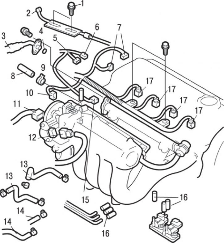
Fig. 3.62. Connecting connectors and hoses to the SOHC engine: 1 – bolt, 10 Nm; 2 – accelerator pedal cable connection; 3 – high pressure fuel hose connection; 4 – O-ring sealing gasket; 5 – coolant temperature sensor connector; 6 – coolant temperature sensor connector (on the indicator); 7 – distributor connectors; 8 – Fuel return hose connection; 9 – brake booster vacuum hose connection; 10 – Accelerator pedal position sensor connector (vehicles with TLC system); 11 – Idle speed controller connector; 12 – Throttle Position Sensor (TPS) connector; 13 – connection of coolant hoses; 14 – connection of heater hoses; 15 – knock sensor connector; 16 – Vacuum hose connections; 17 – injector connector
7. Loosen the bolts and disconnect the cable 2 (Fig. 3.62) of the accelerator pedal.
8. Disconnect the connectors of the throttle position sensor (TPS) 12, idle air control valve 11, accelerator pedal position sensor (vehicles with TLC system) 10, knock sensor 15, coolant temperature sensor 5, coolant temperature sensor (on the pointer) 6, distributor 7 and injectors 17.
9. Loosen the clamp and remove the fuel return hose 8.
10. Loosen the bolts and disconnect the high-pressure fuel hose 3 and the O-ring seal 4.
11. Disconnect the brake booster vacuum hose 9.
12. Disconnect the vacuum hoses 16.
13. Loosen the clamps and disconnect the coolant hoses 13.
14. Loosen the clamps and disconnect the heater hoses 14.
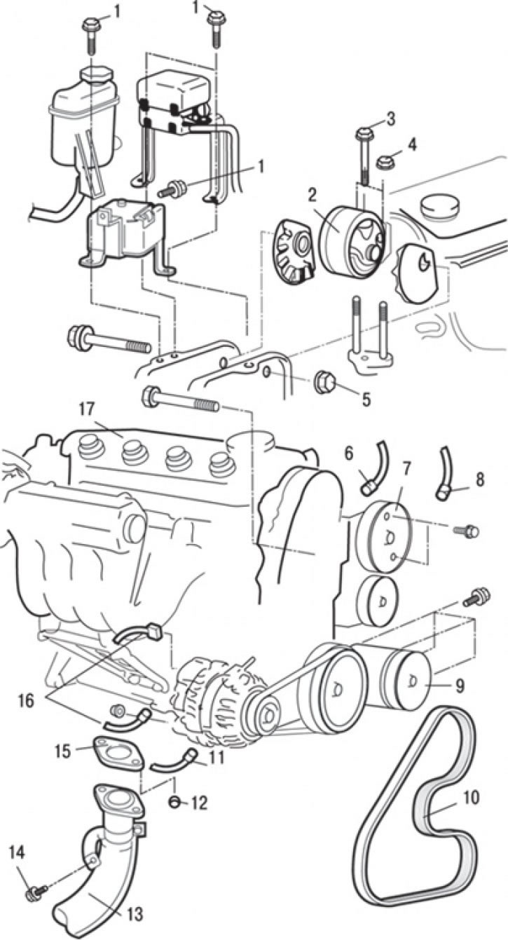
Fig. 3.63. SOHC engine: 1 – bolts; 2 – engine support bracket; 3 – bolt, 62 Nm; 4 – nut, 62 Nm; 5* – nut, 118 Nm; 6 – connector of the sensor (switch) of fluid pressure in the hydraulic system of the power steering; 7 – Power steering pump mount; 8 – air conditioning compressor connector; 9 – Air conditioning compressor mount; 10 – Power steering pump and air conditioning compressor drive belt; 11 – oil pressure switch sensor connector; 12 – nut, 49 Nm; 13-intake pipe of the exhaust gas system; 14 – bolt, 50 Nm; 15 – gasket; 16 – Generator connectors; 17 – engine assembly
15. Disconnect the connectors of the sensor (switch) 6 (Fig. 3.63) of the fluid pressure in the hydraulic system of the power steering, the air conditioner compressor 8, the sensor-switch 11 of the oil pressure and the generator 16.
16. Loosen the tension and remove the belt 10 of the power steering pump and air conditioning compressor drive.
17. Loosen the bolts and remove the power steering pump together with the hoses connected to it.
Attention! Tie the removed power steering pump assembly with bracket and hoses with wire and place it so that it does not interfere with the removal and installation of the engine assembly.
18. Disconnect the air conditioning compressor wire connector and remove the compressor from the bracket with the hoses connected.
Caution! Tie the removed compressor with wire and place it in a place where it will not interfere with the removal and installation of the engine.
19. Loosen the nuts, disconnect the exhaust pipe 13 and remove the gasket 15.
20. Remove bolts 1.
21. Place a hydraulic jack under the engine.
Caution! The fastening points marked with the (*) symbol must first be pre-tightened and then finally tightened after the vehicle has been lowered to the ground (in an unloaded state).
22. Remove the special tool used to remove the gearbox from the engine.
23. Secure the engine to the crossbar and hang it on a hoist or similar device.
24. Insert a wooden block between the jack support foot and the engine oil pan and lift the engine slightly to relieve the support; remove the engine mount bracket.
25. Check that all wires (electrical connectors), hoses, etc. are disconnected from the engine, and then slowly lift the engine upwards from the engine compartment.
Installation
Installation is carried out in the reverse order of removal, taking into account the following.
1. When installing the motor, carefully check that the wires, hoses and wire connectors are not pinched.
2. Place a hydraulic trolley jack under the engine (inserting a wooden block between the jack support foot and the engine oil pan) and install the engine support bracket, adjusting the engine position using the jack.
3. Support the engine with a jack and disconnect the hoist.
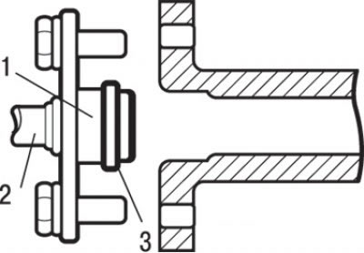
Fig. 3.44. Installing the high pressure fuel hose: 1 – place of lubrication with engine oil; 2 – high pressure fuel hose; 3 – O-ring gasket
4. When installing the high pressure fuel hose, lubricate the O-ring with a small amount of clean engine oil (see Fig. 3.44).
Caution: Do not allow oil to enter the fuel rail.
5. While slightly turning the flange of the fuel hose to the right and left, carefully insert it into the fuel rail so as not to damage the O-ring seal. After installation, check that the hose rotates smoothly in the fuel rail.
6. If the hose flange sticks when turning, the cause may be damage to the O-ring. Disconnect the flange (assembled with the hose) from the fuel rail and inspect the gasket for damage, then insert it back and check for smooth turning.
7. Tighten the mounting bolts.
8. Install the radiator.
9. Install the gearbox.
10. Adjust the accelerator pedal cable.
11. Fill the cooling system with coolant.
12. Adjust the drive belt tension.
13. Install the hood.