



Contents: Removal ⤓ Installation ⤓
Removal
1. Disconnect the cable from the negative terminal of the battery.
2. Remove the protective cover.
3. Remove the engine mount bracket.
4. Remove the crankshaft pulley.
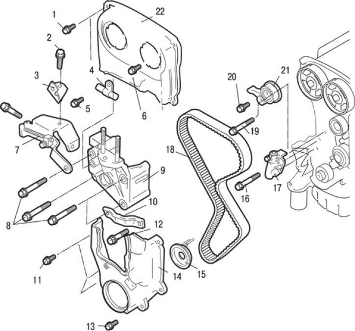
Fig. 3.53. DOHC engine timing belt: 1 – bolt, 9 Nm; 2 – bolt, 25 Nm; 3 – Power steering hose mounting bracket; 4 – Power steering hose clamp; 5 – bolt, 25 Nm; 6 – bolt, 10–12 Nm; 7 – generator adjustment bar; 8 – bolts, 49 Nm; 9 – Engine support bracket; 10 – Power steering pump mounting bracket; 11 – bolt, 9 Nm; 12 – bolt, 49 Nm; 13 – bolt, 9 Nm; 14 – lower timing belt cover; 15 – flange; 16 – bolt, 12–15 Nm; 17 – Automatic timing belt tensioner; 18 – timing belt of the gas distribution mechanism; 19 – bolt, 44 Nm; 20 – bolt, 48 Nm; 21 – timing belt tensioner and bracket assembly; 22 – Upper timing belt cover
5. Loosen the bolt and remove bracket 3 (Fig. 3.53) securing the power steering hose.
6. Loosen the bolt and remove clamp 4 securing the power steering hose.
7. Loosen the bolts and remove the adjusting bar 7 from the generator.
8. Loosen the bolts and remove the upper cover 22 of the timing belt.
9. Loosen the bolts and remove the lower cover 14 of the timing belt.
10. Remove flange 15.
11. Loosen the bolts and remove the power steering pump mounting bracket 10.
12. Loosen the bolts and remove the engine support bracket 9.
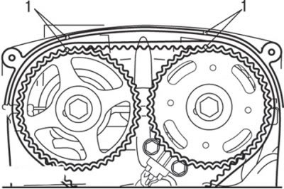
Fig. 3.54. Alignment of timing marks (1) with pointers on DOHC engines
13. Turn the crankshaft and align the timing marks as shown in Fig. 3.54.
Caution: Always turn the crankshaft clockwise only.
14. Loosen the central tensioner roller mounting bolt and remove the timing belt.
Attention! If the timing belt is reused, it is necessary to apply an arrow with chalk on the reverse (non-working) surface of the belt indicating the direction of rotation (right).
Installation
Installation is carried out in the reverse order of removal, taking into account the following.
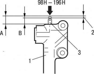
Fig. 3.55. Measuring the rod displacement: A – distance when the rod is in a free state, mm; B – distance when the rod is recessed, mm; 1 – tensioner; 2 – movement (up to 1 mm); 3 – push rod
1. Apply a force of 98–196 N to the automatic tensioner rod, resting it against any hard surface (concrete, metal, etc.), and measure the movement of the rod, which should be no more than 1 mm (Fig. 3.55).
2. If the travel value is beyond the specified limit, replace the automatic tensioner.
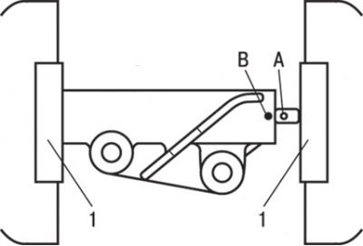
Fig. 3.56. Compressing the tensioner in a vice (1) to align holes A and B
3. Place the automatic tensioner in a vice as shown in Fig. 3.56 and, being careful not to damage (bend) the push rod, squeeze the automatic tensioner until hole A aligns with hole B.
Caution: Perform this operation carefully and slowly to avoid damaging the automatic tensioner.
4. Insert the locating pin into the aligned holes.
Attention! When replacing the tensioner with a new one, the installation pin must already be inserted into the holes.
5. Install the automatic tensioner to the engine.
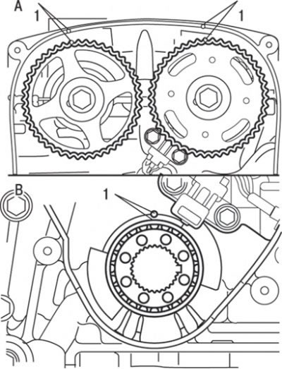
Fig. 3.57. Alignment of timing marks with pointers on DOHC engines: A - camshaft pulleys; B – crankshaft pulley; 1 – installation marks
6. Align the timing marks on both camshaft pulleys and the crankshaft with the corresponding fixed indicators (Fig. 3.57).
7. Loosen the center bolt securing the tensioner roller.
8. Turn the crankshaft pulley half a tooth counterclockwise.
9. Place the drive belt on the exhaust camshaft pulley and secure the belt to this pulley using a clamp.
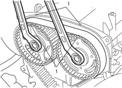
Fig. 3.58. Using two open-end wrenches to align the timing marks (1)
10. Place the timing belt on the camshaft pulley of the intake valves; using two open-end wrenches, align the timing marks as shown in Fig. 3.58.
11. Secure the drive belt to the other pulley with another clamp.
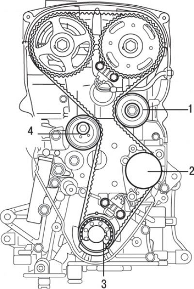
Fig. 3.59. Location of the timing belt on the engine pulleys: 1 – guide roller; 2 – water pump pulley; 3 – crankshaft pulley; 4 – tensioner roller
12. Place the timing belt sequentially on the guide roller, water pump drive pulley, crankshaft pulley and tensioner roller (Fig. 3.59).
13. Remove the clamps.
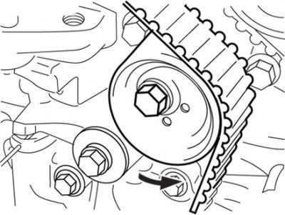
Fig. 3.60. Direction of movement of the tensioner roller for belt pre-tensioning
14. Move the tensioner roller in the direction of the arrow and tighten the mounting bolt (Fig. 3.60).
[The text of the article was obtained from the website: MitsubishiMan]
15. Make sure all alignment marks are aligned.
16. Adjust the timing belt tension by turning the crankshaft 1/4 turn counterclockwise and then returning it to its original position by turning it clockwise, making sure that all timing marks are aligned.
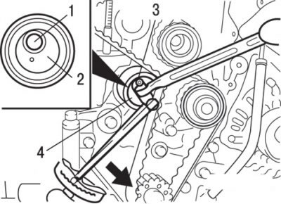
Fig. 3.61. Adjusting the timing belt tension: 1 – fixing bolt; 2 – pin hole; 3 – special tool MD998767; 4 – tensioner roller
17. Loosen the tensioner roller fixing bolt and, using the special tool and torque wrench, tighten the timing belt, then tighten the fixing bolt to a torque of 2.5–4.0 N·m (Fig. 3.61).
Caution: When tightening the locking bolt, make sure that the tensioner roller does not move at this time.
18. Remove the locating pin (2mm hex key) from the automatic tensioner. Make sure the pin can be removed easily.
19. Turn the crankshaft clockwise 2 turns, wait at least 5 minutes, make sure that the installation pin can also be easily removed or inserted into the hole of the automatic tensioner.
Attention! Even if the installation pin is not installed in the aligned holes, it is quite sufficient if the rod protrudes from the tensioner within 3.8–4.5 mm.
20. If the protrusion is not within the nominal value, repeat the belt tensioning operations. Make sure that all timing marks are aligned.
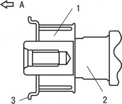
Fig. 3.52. Flange location: A - front part of the engine; 1 – crankshaft pulley; 2 – crankshaft; 3 – flange
21. Install the flange as shown in Fig. 3.52.
22. Install the lower protective cover.
23. Install the engine mount bracket.
24. Install the crankshaft pulley.