
Removing
1. Disconnect a wire from the negative plug of the storage battery.
2. Remove the lower left protective cover.
3. Remove the engine support bracket.
4. Remove the crankshaft pulley.
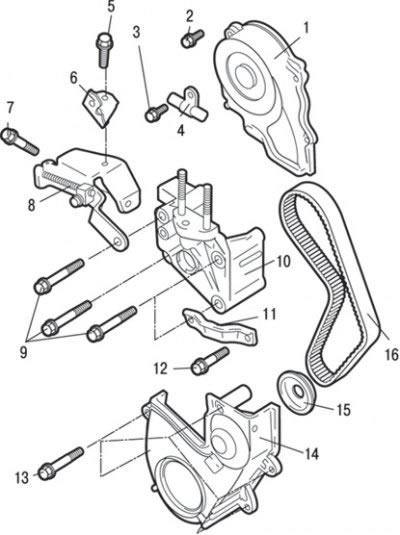
Pic. 3.48. Timing belt: 1 - the upper casing of the timing belt; 2 - bolt, 10–12 Nm; 3 - bolt, 25 Nm; 4 – a collar of fastening of a hose of the amplifier of a steering; 5 - bolt, 25 Nm; 6 – an arm of fastening of a hose of the amplifier of a steering; 7 - bolt, 20–25 Nm; 8 - generator bracket; 9 - bolts, 49 Nm; 10 – an arm of a support of the engine; 11 – an arm of fastening of the pump of the amplifier of a steering; 12 - bolt, 49 Nm; 13 - bolt, 10–12 Nm; 14 - the lower casing of the timing belt drive; 15 - flange; 16 - timing belt drive
5. Turn away a bolt and remove an arm 6 (pic. 3.48) power steering hose fittings.
6. Turn away a bolt and remove a collar 4 fastenings of a hose of the hydraulic booster of a steering.
7. Turn away bolts and remove an arm 8 of the generator.
8. Turn away screws and remove the top casing 1 of a belt of a drive of the gas-distributing mechanism.
9. Turn away bolts and remove the bottom casing 14 of a belt of a drive of the gas-distributing mechanism.
10. Remove flange 15.
11. Turn away a bolt and remove an arm 11 fastenings of the pump of the hydraulic booster of a steering.
12. Turn away bolts and remove an arm 10 of a support of the engine.
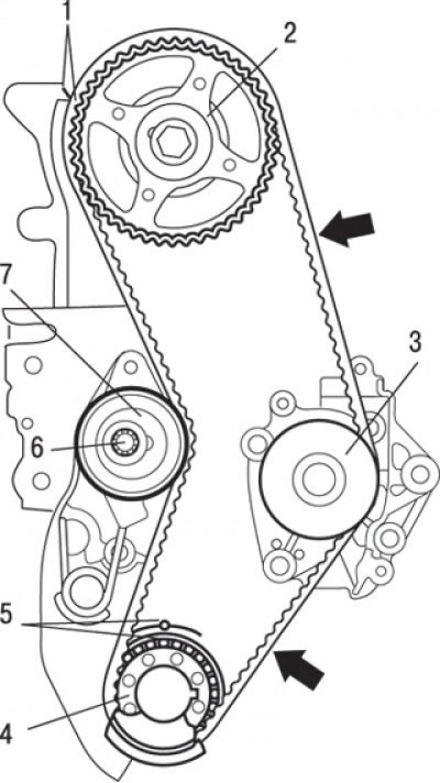
Pic. 3.49. Alignment of the alignment marks on the camshaft pulley and the crankshaft pulley with the corresponding fixed marks when installing the piston of the 1st cylinder at TDC of the compression stroke (the arrows indicate the working branches of the belt): 1 - installation marks; 2 - camshaft pulley; 3 - water pump pulley; 4 - crankshaft pulley; 5 - installation marks; 6 - bolt, 24 Nm; 7 - timing belt tensioner
13. Turn the crankshaft clockwise until the alignment marks on the camshaft pulley and crankshaft pulley are aligned with the corresponding fixed marks and set the piston of the 1st cylinder to TDC of the compression stroke (pic. 3.49).
Attention! Always turn the crankshaft clockwise only.
14. Loosen the adjusting bolt of the timing belt tensioner.
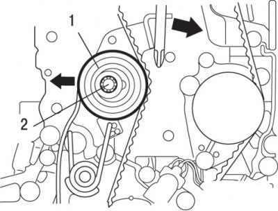
Pic. 3.50. Using a screwdriver to move the timing belt tensioner back: 1 - timing belt tensioner; 2 - bolt
15. Use a screwdriver to fully push back (in the direction of the arrow) timing belt tensioner, as shown in fig. 3.50.
16. Temporarily tighten the adjusting bolt.
17. Remove the timing belt.
Attention! If the timing belt is reused, it must be chalked on the reverse (non-working) belt surface an arrow indicating the direction of rotation (right).
Installation
Installation is carried out in the reverse order of removal, taking into account the following.
1. Insert a screwdriver as shown in fig. 3.50, fully push back (in the direction of the arrow) timing belt tensioner and then temporarily tighten the adjusting bolt.
2. Align the alignment marks on the crankshaft and camshaft pulleys with the corresponding fixed marks.
3. Making sure the working branch (side) belt has been tensioned, install the timing belt in the following order:
- crankshaft pulley;
- water pump pulley;
- camshaft pulley;
- tensioner roller.
After installing the timing belt, try turning the crankshaft pulley counterclockwise with force, and then check the belt tension and match the alignment marks.
4. Loosen the tensioner pulley adjusting bolt 1/2 to 1/4 turn to allow the tensioner spring to move the idler and tension the belt.
5. Turn the crankshaft clockwise 2 turns and make sure that the alignment marks are aligned (see fig. 3.49).
Attention! Since the purpose of this operation is to ensure the correct tension of the timing belt due to the moment created by the camshaft cams, it is necessary to turn the engine crankshaft only clockwise. Never turn the crankshaft counterclockwise.
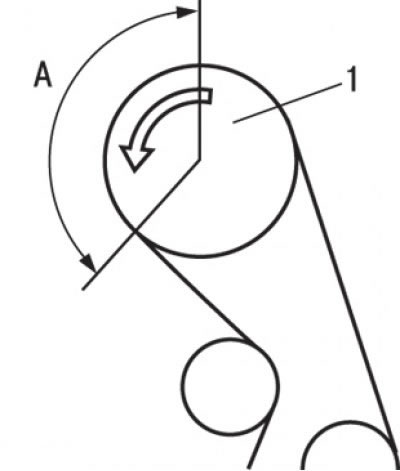
Pic. 3.51. Sector (A), in which it is necessary to check the absence of protrusion of the teeth of the timing belt over the pulley (1) camshaft
6. It is necessary to check the absence of protrusion of the teeth of the timing belt over the camshaft pulley in sector A, indicated in fig. 3.51, and the correctness of its engagement on both pulleys. After that, tighten the tensioner roller adjusting bolt to the appropriate torque.
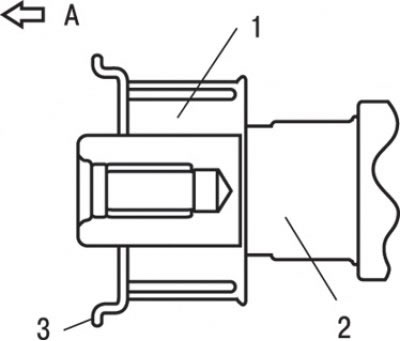
Pic. 3.52. Flange location: And – a forward part of the engine; 1 - crankshaft pulley; 2 - crankshaft; 3 - flange
7. Install the flange as shown in fig. 3.52.
8. Install the bottom left guard.
9. Install the engine support bracket.
10. Install the crankshaft pulley.