



Contents: Removal ⤓ Installation ⤓
Removal
1. Disconnect the cable from the negative terminal of the battery.
2. Remove the timing belt.
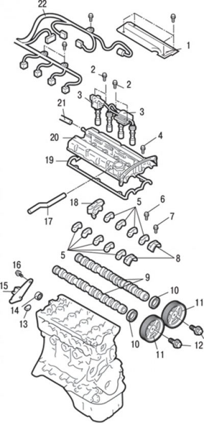
Fig. 3.15. Camshafts and camshaft seals of the DOHC engine: 1 – central cover; 2 – bolts, 10 Nm; 3 – ignition coil assembly; 4 – bolt, 3.4 Nm; 5 – camshaft bearing cap; 6 – bolt, 10–12 Nm; 7 – bolt, 21–25 Nm; 8 – front camshaft bearing caps; 9 – camshafts; 10 – camshaft oil seal; 11 – camshaft pulley; 12 – bolts, 88 Nm; 13 – semicircular plug; 14 – O-ring seal; 15 – ignition system malfunction sensor assembly; 16 – bolt, 12–15 Nm; 17 – Positive crankcase ventilation (PCV) pipe; 18 – rear cover of the camshaft bearing; 19 – cylinder head cover gasket; 20 – cylinder head cover; 21 – connection of the crankcase ventilation hose; 22 – Engine management system wiring harness
3. Loosen the bolts and remove the central cover 1 (Fig. 3.15).
4. Unscrew the bolts and remove the ignition coils 3 together with the high-voltage wire tips.
5. Disconnect crankcase ventilation hose 21 and positive crankcase ventilation (PCV) system pipe 17 from the cylinder head cover.
6. Remove the bolts, disconnect the electrical connectors and remove the engine management system wiring harness 22.
7. Loosen the bolt and remove the ignition system malfunction sensor 15 as an assembly.
8. Loosen the bolts and remove the cylinder head cover 20 together with the gasket 19.
9. Remove the semicircular plug 13.
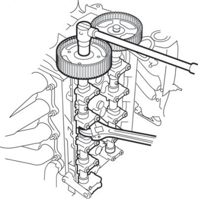
Fig. 3.16. Unscrewing the camshaft pulley mounting bolt
10. Holding the hexagonal parts of the camshafts with a wrench, unscrew the bolts securing the camshaft pulleys and remove the pulleys (Fig. 3.16).
Caution: To avoid damaging the camshaft pulley, do not hold it with a wrench to prevent it from turning.
11. Remove the oil seals 10 (see Fig. 3.15) of the camshafts.
12. Remove the O-ring 14.
13. Loosen the bolts and remove the front 8 camshaft bearing covers.
14. Loosen the bolts and remove the rear cover 18 of the camshaft bearing.
15. Evenly and gradually unscrew the camshaft cover mounting bolts, remove covers 5 and camshafts 9.
Installation
Installation is carried out in the reverse order of removal, taking into account the following.
1. Apply a layer of engine oil to the bearing journals and camshaft lobes.
2. Place the camshafts in the bearing surfaces of the cylinder head.
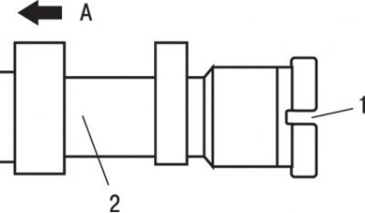
Fig. 3.17. Location of the groove on the exhaust camshaft: A – camshaft pulley side; 1 – groove; 2 – exhaust camshaft
3. Do not mix up the camshafts. There is a groove on the rear end of the exhaust camshaft (Fig. 3.17).
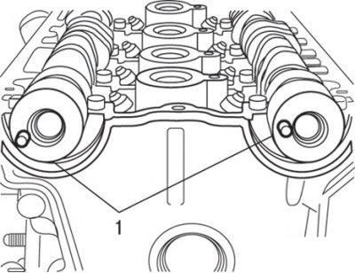
Fig. 3.18. Location of the dowel pins (1) when installing the camshafts
4. Position the camshaft dowel pins as shown in Fig. 3.18.
5. Correctly position the recesses for tightening the camshaft bearing cap bolts.
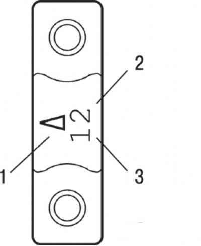
Fig. 3.19. Location of identification marks on the camshaft bearing cap: 1 – label "Front"; 2 – camshaft bearing cap number; 3 – identification symbol
6. Check the camshaft identification symbols and bearing cap numbers, install them taking into account their compliance and the orientation of the "Front" mark (Fig. 3.19).
The inlet camshaft has the identification symbol "I", the exhaust camshaft has the symbol "E".
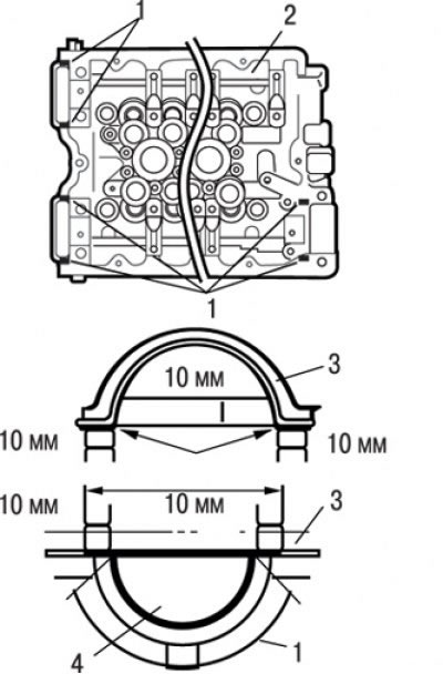
Fig. 3.20. Places to apply sealant to the cylinder head: 1 – places of application of sealant ЗМ ATD Part # 8660; 2 – cylinder head; 3 – cylinder head cover gasket; 4 – semicircular plug
7. Apply 3M ATD Part # 8660 or equivalent sealant to the cylinder head locations shown in Fig. 3.20.
8. After pre-tightening the camshaft bearing caps in 2–3 steps, tighten them finally to the specified torque:
The original material is here MitsubishiMan.ru
- 21–25 Nm – front and rear covers;
- 10–12 Nm – other caps.
9. Make sure the valve rocker arms are correctly oriented in relation to the valve stems and hydraulic lifters.
10. Using a special tool or a tubular mandrel, install the O-ring.
11. Lubricate the working edge of the camshaft oil seal with engine oil.
12. When pressing in the camshaft oil seal, use a special tool.
13. To prevent the pulley from turning, use a special tool (the same one used for removal) and then tighten the bolts to a torque of 88 N·m.