



Disassembly
The main preliminary operations that need to be taken into account are given in the sections "Replacing oil seals" and "Replacing the cylinder head gasket" chapters "MPI engines - mechanical part".
The parts are removed in the order of numbers shown in the figure "Removing the rocker arm shaft and camshaft".
When removing parts, pay attention to the following operations:
1. Removing the rocker arm shafts and valve rocker arms.
Attention:
- Do not disassemble the rocker arm shaft assembly with the rocker arms unless absolutely necessary.
- If it is necessary to disassemble the rocker arm shaft, arrange the rocker arms according to the cylinder number and intake/exhaust valves so as not to mix them up during assembly.
2. Removing the camshaft.
Caution: Be careful not to damage the camshaft when removing it from the cylinder head.
Examination
Checking the camshaft
1. Checking the axial clearance of the camshaft.
a) Measure the axial clearance of the camshaft when the shaft is installed in the cylinder head.
Axial clearance:
- nominal - 0.05 - 0.08 mm
- maximum permissible - 0.20 mm
b) If the axial clearance of the camshaft is greater than the maximum permissible value, replace the camshaft and cylinder head.
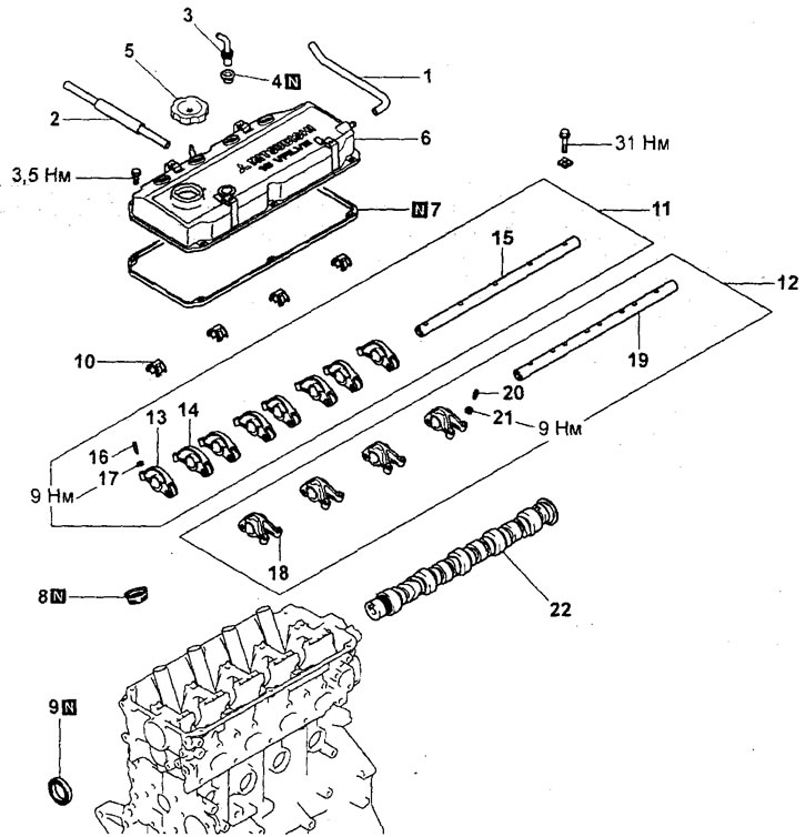
Removal the rocker arm shaft and camshaft (engine 4G93).1 - ventilation hose, 2 - positive crankcase ventilation hose, 3 - positive crankcase ventilation valve, 4 - positive crankcase ventilation valve gasket, 5 - oil filler cap, 6 - cylinder head cover, 7 - cylinder head cover gasket, 8 - cylinder head cover seal (under spark plugs), 9 - camshaft oil seal, 10 - rocker arm shaft spring, 11 - rocker arm shaft assembly (for intake valves), 12 - rocker arm shaft assembly (for exhaust valves), 13 - valve rocker arm "B", 14 - valve rocker arm "A", 15 - rocker arm shaft, 16 - adjusting screw, 17 - lock nut, 18 - valve rocker arm "C", 19 - rocker arm shaft, 20 - adjusting screw, 21 - lock nut, 22 - camshaft.
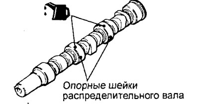
2. Inspect the camshaft journals, check for scoring. If scoring is present, replace the camshaft, check the condition of the shaft bed in the cylinder head and clean the oil passage channel in the cylinder head.
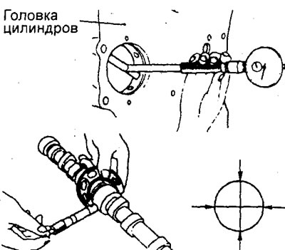
3. Check the diameter of the camshaft bearing pins. If their measured value does not correspond to the nominal value, then check the oil clearance between the journal and the camshaft bearing.
Nominal value:
- Engine 4G15 - 45.93 - 45.94 mm
- Engine 4G93 - 45.0 mm
4. Determine the camshaft oil clearance. If the clearance in any bearing exceeds the maximum permissible value, replace the camshaft and cylinder head.
Oil clearance:
- Nominal - 0.05 - 0.09 mm
- Maximum permissible - 0.12 mm
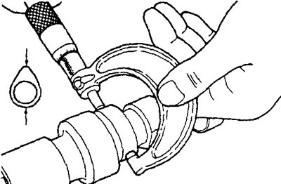
5. Check the condition of the camshaft cam surface.
6. Measure the height of the camshaft lobes and, if the measured value is less than the maximum permissible value, replace the camshaft.
Height of cams:
Engine 4G15:
| Cam | Nomin. | Limit. |
| Inlet | 37.30 mm | 36.80 mm |
| Outlet | 37.16 mm | 36.66 mm |
Engine 4G93:
| Cam | Nomin. | Limit. |
| Inlet | 37.53 mm | 37.03 mm |
| Outlet | 37.64 mm | 37.14 mm |
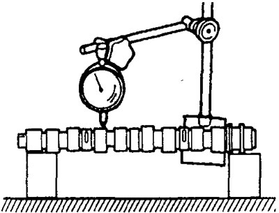
7. Install the camshaft on the supports (on the outer bearing journals). Measure the shaft runout on the middle journal. If the runout exceeds the maximum permissible value, replace the camshaft.
Camshaft runout:
- nominal less than — 0.02 mm
- maximum permissible - 0.10 mm
Checking the rocker arms and rocker shafts
1. Check the surface of the valve rocker arm pressure roller and rocker arm tappet; replace the rocker arm if there is significant local wear, damage, or scoring.
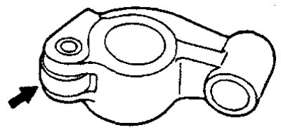
2. Check the rotation of the pressure roller and replace the valve rocker arm if it is jammed or has excessive play.
3. Measure the inner diameter of the valve rocker arm bushing (under the axle), replace the rocker arm if there is increased wear or scoring.
4. Inspect the outer circumference of the rocker shaft where the rocker arm is mounted for uneven or excessive wear. Replace the rocker shaft if there is obvious damage or scoring.
5. Check that the oil holes in the rocker shaft are not clogged. Clean the oil holes if necessary.
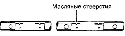
6. Check the clearance between the rocker arm bushing and the rocker arm shaft. If the clearance exceeds the nominal value, replace the rocker arms and the rocker arm shaft.
Nominal clearance - 0.02 - 0.05 mm
Assembly
Installation of parts is carried out in the reverse order of removal.
Original source of information (MitsubishiMan.ru)
When installing parts, please pay attention to the following operations:
Caution: Apply engine oil to all moving parts during assembly.
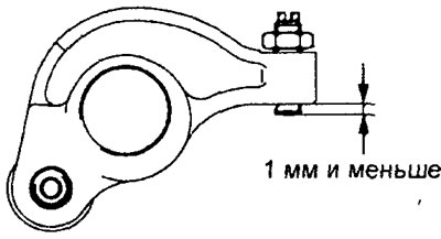
1. Installing the adjusting screw.
Install the screw onto the rocker arm and temporarily secure it with the nut.
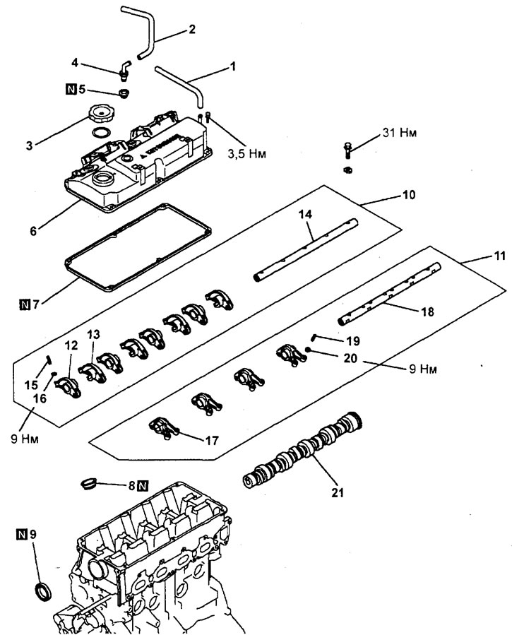
Removal the rocker arm shaft and camshaft (engine 4G15).1 - ventilation hose, 2 - positive crankcase ventilation hose, 3 - oil filler cap, 4 - positive crankcase ventilation valve, 5 - positive crankcase ventilation valve gasket, 6 - cylinder head cover, 7 - cylinder head cover gasket, 8 - cylinder head cover seal (under spark plugs), 9 - camshaft oil seal, 10 - rocker arm shaft assembly (for intake valves), 11 - rocker arm shaft assembly (for exhaust valves), 12 - valve rocker arm "A", 13 - valve rocker arm "B", 14 - rocker arm shaft, 15 - adjusting screw, 16 - lock nut, 17 - valve rocker arm "C", 18 - rocker arm shaft, 19 - adjusting screw, 20 - lock nut, 21 - camshaft.
Make sure that the end of the screw is flush with the surface of the rocker arm or that its protrusion relative to this surface does not exceed 1 mm.
2. Installing the camshaft. Before installing the camshaft into the cylinder head, lubricate the bearing journals and cams of the camshaft with engine oil.
3. Installing the valve rocker arms, rocker arm shaft and rocker arm shaft spring.
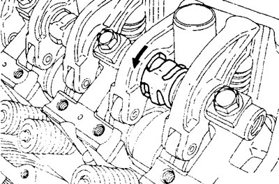
a) Install and lightly tighten the intake rocker arm shaft bolts so that neither rocker arm presses on the valves.
Note: Before installing the rocker arm shafts, check the following:
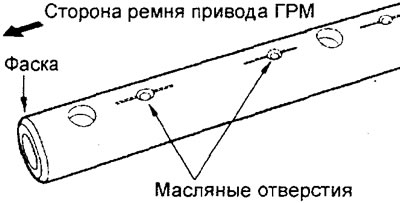
- The rocker arm shaft with four bolt holes is installed on the intake valve side.
- The rocker arm shaft oil holes face downwards during installation (located on the cylinder head side).
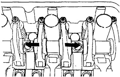
b) Before tightening the rocker arm shaft mounting bolts, move the corresponding rocker arms in the directions indicated by the arrows in the figure.
Note: After moving the rocker arms, make sure they touch the rocker arm shaft mounting tabs on the cylinder head.
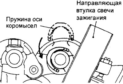
c) Install the rocker spring on top of the axle so that it is at a right angle to the spark plug guide sleeve.
Note: The rocker shaft springs must be installed before installing the rocker shaft with the exhaust rocker arms.
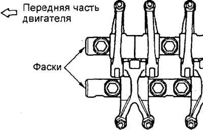
d) Make sure that the chamfers on each rocker arm axle are positioned as shown in the figure.
4. Installing the camshaft oil seal.
Note: The camshaft oil seal installation procedure is described in the section "Replacing oil seals" chapters "MPI engines - mechanical part".
Other final operations that need to be taken into account are given in the sections "Replacing oil seals" and "Replacing the cylinder head gasket" chapters "MPI engines - mechanical part".