
Removing
Perform the following operations before beginning to remove parts.
A) Release residual pressure from the high pressure fuel line (see chapter "fuel injection system (MPI)").
b) Remove the engine crankcase guard.
V) Drain coolant and engine oil.
G) Remove the air filter.
d) (Engine 4G93) Remove the thermostat housing assembly.
e) (Engine 4G15) Remove the battery and battery tray.
Removal of parts is carried out in the order of the numbers indicated in the figure "Replacing the cylinder head gasket".
When removing parts, pay attention to the following operations:
1. (Engine 4G93) Removing the upper radiator hose.
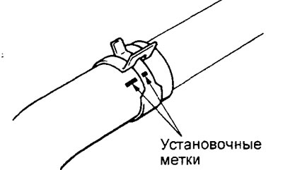
Before disconnecting the upper radiator hose, mark the relative position on the hose and hose clamp.
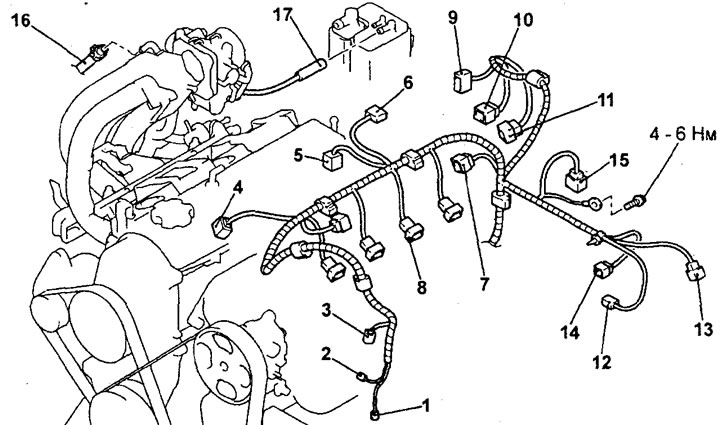
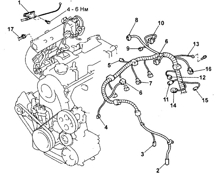
Replacing the cylinder head gasket (4G15 engine). 1 - connector of the electromagnetic clutch of the air conditioning compressor, 2 - connector of the sensor-switch for fluid pressure in the hydraulic system of the power steering, 3 - connector of the crankshaft position sensor, 4 - connector of the knock sensor, 5 - connector of the solenoid valve of the exhaust gas recirculation system, 6 - absolute sensor intake manifold pressure (with integrated intake manifold air temperature sensor), 7 ignition coil connector, 8 - injector connector, 9 - throttle position sensor connector, 10 - idle speed control servo connector, 11 - canister purge solenoid valve connector, 12 coolant temperature gauge sensor connector, 13 oxygen sensor connector, 14 coolant temperature sensor connector, 15 camshaft position sensor connector, 16 brake booster vacuum hose connection, 17 EVAP vacuum hose connection (remove the cylinder head cover and gasket, exhaust manifold and inlet pipe of the cooling system).
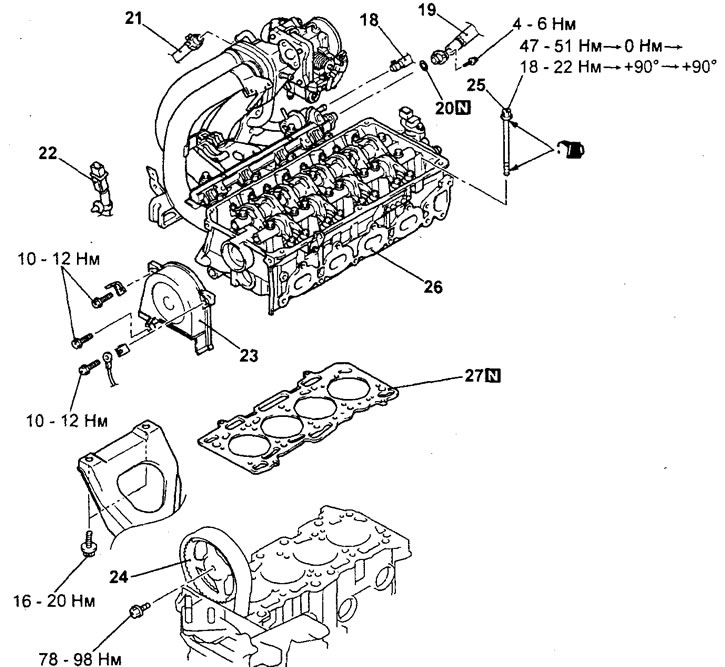
Replacing the cylinder head gasket (4G15 engine, continued). 18 - fuel return hose connection, 19 - high pressure fuel hose flange connection, 20 - O-ring, 21 - heater hose connection, 22 - knock sensor connector retainer, 23 - timing belt front upper cover, 24 - camshaft pulley and belt timing drive assembly, 25 - cylinder head bolt, 26 - cylinder head assembly, 27 - cylinder head gasket.
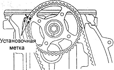
2. Removing the camshaft pulley and timing belt assembly.
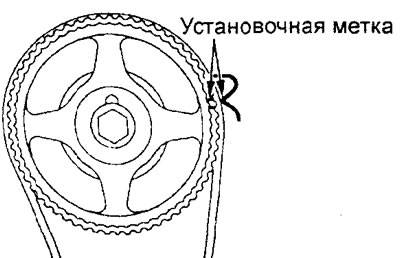
A) Turn the camshaft clockwise until the timing mark on the camshaft pulley aligns with the corresponding timing mark, and set the No. 1 cylinder piston to TDC on the compression stroke.
Caution: Always turn the crankshaft in a clockwise direction only.
Engine 4G15.
Engine 4G93.
b) Using a band or wire, secure the timing belt to the camshaft pulley in the position as shown in the illustration.
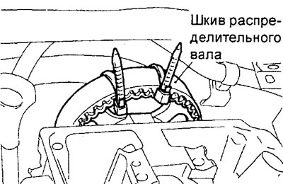
V) Secure the camshaft pulley against rotation using a special fork holder and special bolts.
Attention: be careful not to rotate the camshaft after removing the pulley.
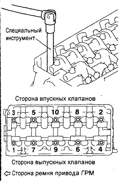
3. Removing the cylinder head.
Using a special tool, loosen the mounting bolts in two or three steps (in the sequence shown in the figure), and then unscrew them, and then remove the cylinder head assembly.
Replacing the cylinder head gasket (4G93 engine). 1 - accelerator pedal cable connection, 2 - air conditioning compressor electromagnetic clutch connector, 3 - power steering fluid pressure switch connector, 4 - crankshaft position sensor connector, 5 - canister purge solenoid valve connector, 6 - coil connector ignition, 7 - injector connector, 8 - throttle position sensor connector, 9 - idle speed control servo connector, 10 - EGR valve servo connector, 11 - coolant temperature sensor connector, 12 - camshaft position sensor connector, 13 - wire connection "masses", 14 - knock sensor connector, 15 - coolant temperature gauge sensor connector, 16 - oxygen sensor connector, 17 - brake booster vacuum hose connection (remove the cylinder head cover and gasket, remove the exhaust manifold).
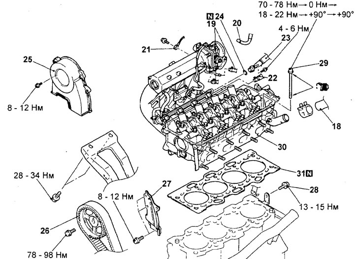
Replacing the cylinder head gasket (4G93 engine, continued).18 - upper radiator hose connection, 19 - heater hose connection, 20 - forced crankcase ventilation hose connection, 21 - wire connection "masses", 22 - fuel return hose connection, 23 - high pressure fuel hose flange connection, 24 - O-ring, 25 - front timing belt upper cover, 26 - camshaft pulley and timing belt assembly, 27 - rear upper timing belt cover Timing, 28 - bolt for fastening the retainer of the inlet pipe of the cooling system, 29 - bolt for fastening the cylinder head, 30 - cylinder head assembly, 31 - cylinder head gasket.
Stop
Installation of details is made in an order, the return to removal.
Pay attention to the following operations when installing parts.
1. Installing the cylinder head gasket.
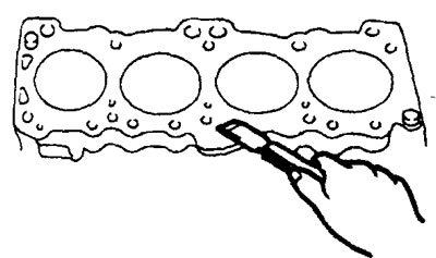
A) Using a special scraper, remove the remnants of the old cylinder head gasket from the cylinder block.
Attention: be careful not to allow gasket material or other foreign parts to enter the cylinders, cooling system channels and lubrication system channels.
b) Degrease the work surface under the gasket on the cylinder block.
V) Check that the correct engine identification mark is on the new cylinder head gasket,
G) Lay the cylinder head gasket on the cylinder block.
Attention: since there is a possibility of improper installation of the cylinder head gasket, check the correct installation of the gasket before installing the cylinder head (coincidence of all holes on the gasket and the cylinder head). If the gasket is installed incorrectly, malfunctions may occur, for example, lack of oil ingress into the cylinder head.
2. Installing the cylinder head assembly.
A) Using a scraper, remove the remnants of the old cylinder head gasket from the cylinder head.
Attention: be careful not to allow gasket material or other foreign particles to enter the cooling system channels and lubrication system channels.
b) When installing the cylinder head bolts, the length of the bolts must be within the allowable value. If the length of the bolts is greater than the maximum allowable value, then the bolts must be replaced.
Maximum allowable value:
4G15 engine - no more than 103.2 mm
4G93 engine - no more than 96.4 mm
V) Lubricate the threads and washers of the cylinder head bolts with a small amount of clean engine oil.
G) Install the cylinder head bolt washers with the chamfered side up as shown.
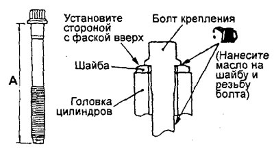
d) Before installation, it is necessary to lubricate the upper surface of the washer and the thread of the bolt with a small amount of engine oil.
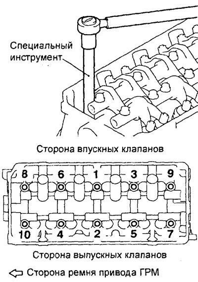
e) Tighten the cylinder head bolts using the angle tightening method in the following order (tightening is carried out in the sequence of numbers indicated in the figure):
4G Engine 15:
- (1) Tighten all bolts to 49±2 Nm in the order shown in the figure;
- (2) Completely loosen all bolts in the reverse order shown in the figure.
- (3) Tighten all bolts to 20±2 Nm in the order shown in the figure;
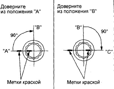
- (4) Tighten all bolts by 90° (1/4 turn, out of position "A" into position "IN") in the order shown in the figure;
- (5) Completely tighten all bolts by 90° (1/4 turn, out of position "IN" into position "WITH") in the order shown in the figure.
4G93 engine:
- (1) Tighten all bolts to 74±2 Nm in the order shown in the figure;
- (2) Completely loosen all bolts in the reverse order shown in the figure.
- (3) Tighten all bolts to 20±2 Nm in the order shown in the figure;
- (4) Tighten all bolts by 90° (1/4 turn, out of position "A" into position "IN") in the order shown in the figure;
- (5) Completely tighten all bolts by 90° (1/4 turn, out of position "IN" into position "WITH") in the order shown in the figure.
Note:
- After tightening, the marks on the bolts and the cylinder head must be in line ("WITH").
- If the cylinder head bolt is turned less than 90° (1/4 turn), then the tightening of the bolt will be insufficient (the reliability of the gas joint will not be ensured).
- If the cylinder head mounting bolt is tightened to a torque exceeding the nominal value, completely unscrew the mounting bolts and follow the bolt tightening procedure, starting from subparagraph "b".
3. Installing the camshaft pulley with timing belt assembly.
A) Install the camshaft pulley, aligning the alignment marks, and fix it from turning with a special fork holder and special bolts. Then tighten the mounting bolt to the specified torque.
Tightening torque - 88±10 N.m
b) Remove the band or wire securing the timing belt to the camshaft pulley.
4. Installation of the O-ring and flange of the high pressure fuel hose.
A) Apply a small amount of engine oil to the sealing lip of the O-ring around its entire circumference.
b) Rotate the flange of the high pressure fuel hose to the right and left, carefully install the hose without damaging the O-ring. After connecting, check that the hose rotates smoothly.
V) If the hose flange does not rotate smoothly, the O-ring may be pinched. Disconnect the high pressure fuel hose flange and check the o-ring for damage, then repeat the installation step "b".
G) Tighten the high pressure fuel hose flange bolts to specification.
Tightening torque - 5±1 N.m
5. (Engine 4G93) Installing the upper radiator hose.
A) When connecting the upper radiator hose, put the hose on the branch pipe until it stops against the protrusion pat-nvbKa, then tighten the clamp.
b) The hose clamp should always be installed in the position in which the clamp was previously installed. Therefore, before installing the clamp, align the alignment marks on the hose clamp and radiator hose, then connect the hose.
After completing the installation of the parts, perform the following operations:
- A) (Engine 4G15) Install the battery tray and battery.
- b) (Engine 4G93) Install the thermostat housing assembly.
- V) Install the air filter.
- G) Fill with coolant and engine oil.
- d) Install the engine crankcase guard.
- e) Adjust the accelerator pedal cable.
- and) Check for fuel leaks.