



Removal
Before you begin removing parts, perform the following operations:
- a) Remove the engine crankcase protective cover.
- b) Remove the support bracket and engine mount assembly.
The parts are removed in the order of numbers indicated in the figures"Removal the crankshaft pulley" and "Timing Belt Replacement".
When removing parts, pay attention to the following operations:
1. Removing the power steering pump and air conditioning compressor drive belt.
a) Loosen the lock nut of the power steering pump and air conditioning compressor drive belt tensioner roller.
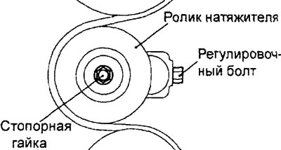
b) Loosen the adjusting bolt to release the belt tension, then remove the belt.
Caution: If the power steering pump and air conditioning compressor drive belt is reused, an arrow indicating the direction of rotation (clockwise) must be chalked on the reverse (non-working) surface of the belt.
1. Removing the generator drive belt,
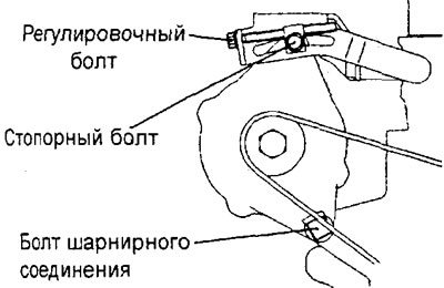
a) Loosen the lock bolt on the generator adjusting bar and the pivot bolt.
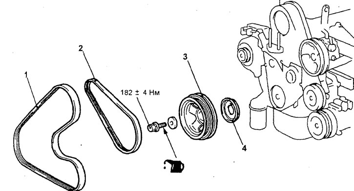
Removal the crankshaft pulley (engine 4G93). 1 - power steering pump and air conditioning compressor drive belt (models with air conditioning), 2 - alternator drive belt, 3 - crankshaft pulley, 4 - guide plate.
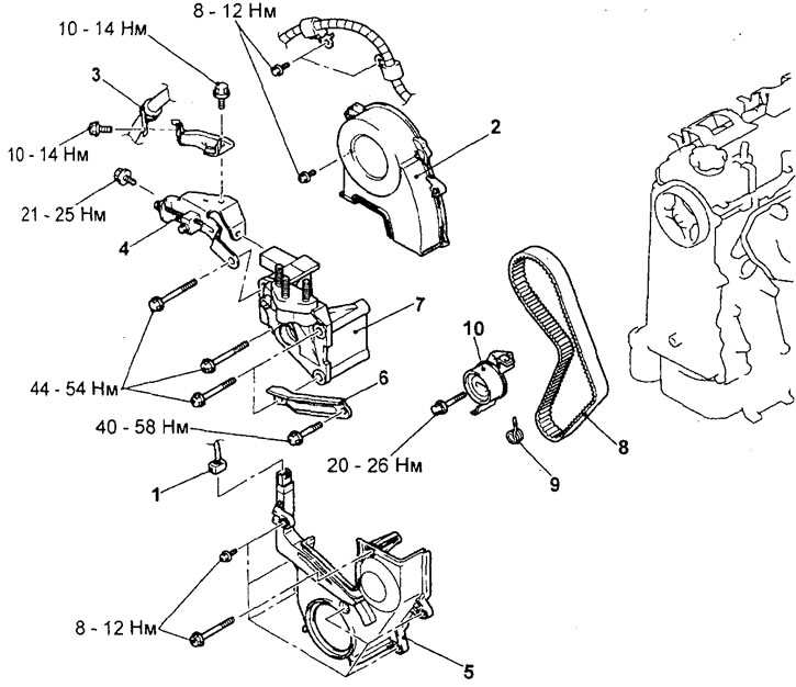
Replacing the timing belt (engine 4G93). 1 - crankshaft position sensor connector, 2 - front upper timing belt cover, 3 - power steering pressure hose retainer, 4 - alternator adjusting bar, 5 - front lower timing belt cover, 6 - power steering pump strut, 7 - engine side support bracket, 8 - timing belt, 9 - tensioner spring, 10 - timing belt tensioner.
b) Turn the adjusting bolt to release the tension of the generator drive belt, then remove the belt.
Caution: If the alternator drive belt is reused, it is necessary to mark an arrow with chalk on the reverse (non-working) surface of the belt indicating the direction of rotation (clockwise).
3. Removing the crankshaft pulley.
Using a special tool, secure the crankshaft pulley from turning and unscrew the crankshaft pulley mounting bolt.
Caution: Secure the special tool securely to prevent it from moving.
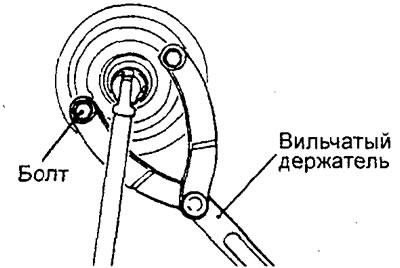
4. Removing the timing belt.
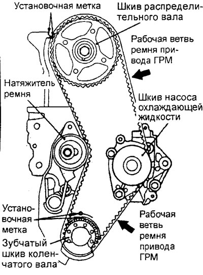
a) Turn the crankshaft clockwise until the timing marks on the camshaft pulley and the crankshaft toothed pulley are aligned with the corresponding timing marks to set the piston of cylinder No.1 to TDC of the compression stroke.
Caution: Always turn the crankshaft clockwise only.
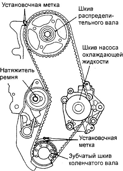
b) Loosen the timing belt tensioner adjusting bolt.
c) Insert a screwdriver into the hole of the tensioner bracket and fully move the timing belt tensioner in the direction shown in the figure
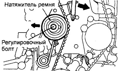
d) Temporarily tighten the tensioner adjusting bolt.
d) Remove the timing belt.
Note: If the timing belt is reused, it is necessary to mark with chalk an arrow on the reverse (non-working) surface of the belt indicating the direction of rotation (clockwise).
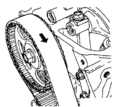
Examination
Note: See the inspection procedure in the "Timing Belt Replacement (4G15 Engine)" section.
Installation
Attention:
- Since water or oil can seriously reduce the life of the timing belt, when removing parts, ensure that the timing belt, pulleys and tensioner bracket are clean and dry, never wash them. Contaminated parts must be replaced.
- If any of the parts are oily, check for oil leaks through the seals (including the front camshaft seal).
- Check the condition and smooth rotation of the tensioner roller.
- If you are installing a timing belt that has been in use, check its condition.
Installation is carried out in the reverse order of removal.
When installing parts, please pay attention to the following operations:
1. Installing the timing belt tensioner.
a) Insert a screwdriver into the hole in the tensioner bracket and fully move the timing belt tensioner in the direction shown in the figure.
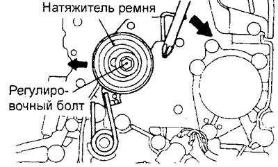
b) Temporarily tighten the tensioner adjusting bolt.
2. Installing the timing belt.
Attention:
- Install the timing belt so that the belt tension does not weaken between the pulleys and rollers.
- Install a used belt so that the arrow on the back of the belt matches the direction of rotation of the belt (clockwise).
a) Check that the marks on the camshaft pulley and the toothed pulley of the crankshaft are aligned with the corresponding installation marks (in this case, the piston of cylinder No.1 will be at TDC of the compression stroke).
b) Install the timing belt in the following order, ensuring that the working branch (side) of the belt is tensioned: crankshaft toothed pulley, coolant pump pulley, camshaft pulley, tensioner roller.
Caution: After installing the timing belt, apply force to the camshaft pulley to turn it counterclockwise and check that the belt is fully tensioned and all timing marks are aligned.
3. Adjusting the timing belt tension.
a) Loosen the adjusting bolt 1/4-1/2 turn so that the timing belt is tensioned by the tensioner spring force.
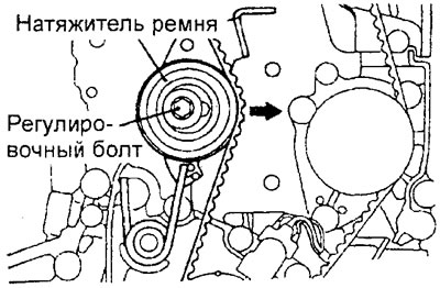
b) Turn the crankshaft in the direction of rotation (clockwise) by 2 turns and make sure that all marks on the pulleys are aligned with the corresponding timing marks.
Caution: Since the purpose of this operation is to apply the appropriate tension force to the working branch of the timing belt using the torque on the camshaft, turn the crankshaft only two revolutions. Do not turn the crankshaft in the opposite direction (counterclockwise).
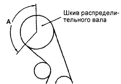
c) Check that there is no protrusion of the timing belt teeth relative to the camshaft pulley in sector "A" shown in the figure, and that normal engagement of the timing belt with the pulleys is ensured. Then tighten the tensioner roller fastening.
3. Installing the front lower timing belt cover.
a) Install the bolt shown in the figure first.
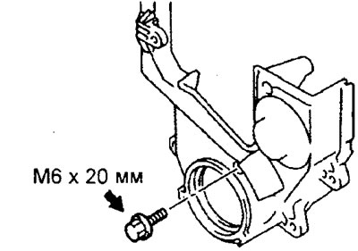
b) Install the remaining bolts and tighten them to the specified torque.
Tightening torque: 10 ±2 Nm
4. Installing the guide plate and crankshaft pulley.
a) Clean and then degrease the surface of the crankshaft pulley that contacts the guide plate.
Note: Degreasing is necessary to improve the mating of parts.
b) Clean the threaded hole in the end of the crankshaft, the end of the shaft, the washer of the pulley mounting bolt and the surfaces in contact with it.
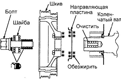
c) Install the guide plate onto the crankshaft, positioning it as shown in the figure.
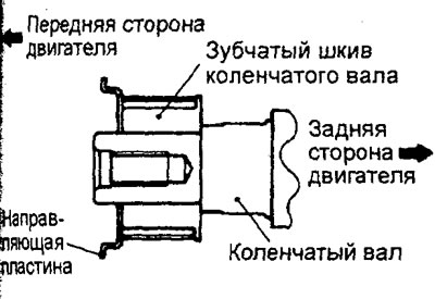
d) Lubricate the mating surface (cone) of the crankshaft nose and the thread of the crankshaft bolt with a minimum amount of engine oil.
d) Before installing the crankshaft pulley mounting bolt, it is necessary to install the bolt washer with the chamfered side facing the bolt.
e) Using the special tool, lock the crankshaft pulley from turning or lock the flywheel from turning, and install the crankshaft pulley mounting bolt.
Caution: Secure the special tool securely to prevent it from turning.
After completing the installation of the parts, perform the following operations:
- a) Install the support bracket and engine mount assembly.
- 6) Install the engine crankcase protective cover.
- c) Adjust the tension of the drive belts of the attachments (see chapter "Maintenance and general check and adjustment procedures").
- d) Install the decorative engine cover.