



Contents: Removal ⤓ Installation ⤓
Removal
Before you begin removing parts, perform the following operations.
a) Release residual pressure from the high-pressure fuel line (see chapter "Fuel injection system (MPI)").
b) Remove the engine crankcase protective cover.
c) Drain the coolant and engine oil.
d) (Engine 4G93) Remove the radiator.
d) Remove the hood.
e) Remove the air filter.
g) Remove the battery and battery tray.
c) (Engine 4G15) Disconnect the accelerator pedal cable
(Information copied from the website MitsubishiMan)
i) Disconnect the exhaust pipe from the exhaust manifold.
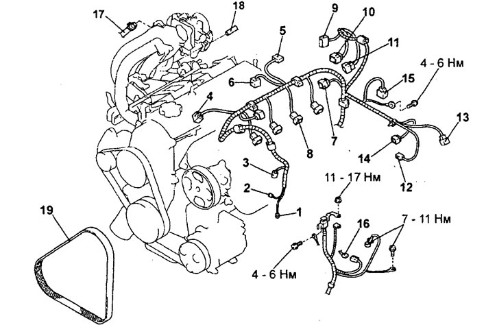
Removal the engine assembly (engine 4G15). 1 - Air conditioning compressor electromagnetic clutch connector, 2 - Power steering hydraulic system fluid pressure switch connector, 3 - Crankshaft position sensor connector, 4 - Knock sensor connector, 5 - Manifold absolute pressure sensor (with integrated manifold air temperature sensor), 6 - EGR electromagnetic valve connector, 7 - Ignition coil connector, 8 - Injector connector, 9 - Throttle position sensor connector, 10 - Idle speed control servo connector, 11 - Evaporative air canister purge electromagnetic valve connector, 12 - Coolant temperature gauge sensor connector, 13 - Oxygen sensor connector, 14 - Coolant temperature sensor connector, 15 - Camshaft position sensor connector, 16 - Battery and engine management system wiring harness connector, 17 - Vacuum hose connection brake booster, 18 - connection of the vacuum hose of the fuel vapor recovery system, 19 - drive belt of the power steering pump and air conditioning compressor.
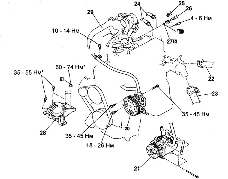
Removal the engine assembly (engine 4G15, continued). 20 - Power steering pump, 21 - Air conditioning compressor, 22 - Upper radiator hose connection, 23 - Lower radiator hose connection, 24 - Heater hose connection, 25 - Fuel return hose connection, 26 - High pressure fuel hose flange connection, 27 - O-ring (remove gearbox), 28 - Engine mount assembly, 29 - Engine assembly.
Note: connections marked with the symbol should first be tightened only preliminarily, and the final tightening to the specified torque should be carried out after the engine has been completely lowered onto the supports.
3. Removing the power steering pump.
Remove the power steering pump from the engine along with the hoses connected to it.
Note: After removal, secure the power steering pump together with the hoses with wire in a place where it will not interfere with or be damaged when removing and installing the engine assembly.
4. Removing the air conditioning compressor.
Disconnect the air conditioner compressor wire connector and remove the compressor from its bracket along with the attached hoses.
Note: After removal, use a wire to hang the air conditioning compressor assembly together with the hoses on the body in a place where they will not interfere with the removal and installation of the engine assembly.
5. Removing the upper and lower radiator hoses.
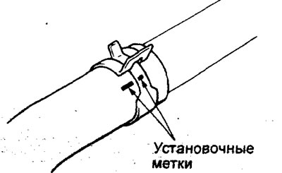
Before disconnecting the upper and lower radiator hoses, place relative position alignment marks on the hose and hose clamp.
The parts are removed in the order of numbers shown in the figure "Removing the complete engine".
When removing parts, pay attention to the following operations:
1. (Engine 4G 15) Removing the power steering pump and air conditioning compressor drive belt.
a) Loosen bolts "A", "B" and "C" of the power steering pump.
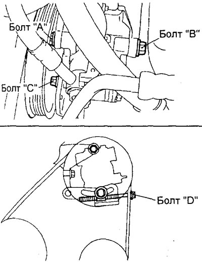
b) Loosen the adjusting bolt "D" to release the belt tension, then remove the belt.
Caution: If the power steering pump and air conditioning compressor drive belt is reused, an arrow indicating the direction of rotation (clockwise) must be chalked on the reverse (non-working) surface of the belt.
2. (Engine 4G93) Removing the power steering pump and air conditioning compressor drive belt.
a) Loosen the lock nut of the power steering pump and air conditioning compressor drive belt tensioner roller.
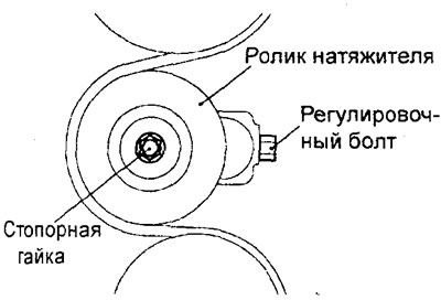
b) Loosen the adjusting bolt to release the belt tension, then remove the belt.
Caution: If the power steering pump and air conditioning compressor drive belt is reused, an arrow indicating the direction of rotation (clockwise) must be chalked on the reverse (non-working) surface of the belt.
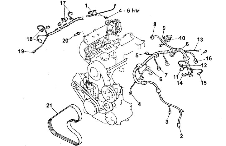
Removal the engine assembly (engine 4G93). 1 - Accelerator pedal cable connection, 2 - Air conditioning compressor electromagnetic clutch connector, 3 - Power steering hydraulic fluid pressure switch connector, 4 - Crankshaft position sensor connector, 5 - Evaporative canister purge electromagnetic valve connector, 6 - Ignition coil connector, 7 - Injector connector, 8 - Throttle position sensor connector, 9 - Idle speed control servo connector, 10 - EGR valve servo connector, 11 - Coolant temperature sensor connector, 12 - Camshaft position sensor connector, 13 - Ground wire connection, 14 - Knock sensor connector, 15 - Coolant temperature gauge sensor connector, 16 - Oxygen sensor connector, 17 - Starter connector, 18 - Generator connectors, 19 - Engine oil pressure sensor connector oil, 20 - brake booster vacuum hose connection, 21 - power steering pump and air conditioning compressor drive belt.
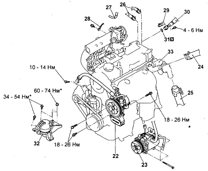
Removal the engine assembly (engine 4G93, continued).22 - Power steering pump, 23 - Air conditioning compressor, 24 - Upper radiator hose connection, 25 - Lower radiator hose connection, 26 - Heater hose connection, 27 - Positive crankcase ventilation hose connection, 28 - Ground wire connection, 29 - Fuel return hose connection, 30 - High pressure fuel hose flange connection, 31 - O-ring (remove gearbox), 32 - Engine mount assembly, 33 - Engine assembly.
Note: connections marked with the symbol should first be tightened only preliminarily, and the final tightening to the specified torque should be carried out after the engine has been completely lowered onto the supports.
3. Removing the power steering pump.
Remove the power steering pump from the engine along with the hoses connected to it.
Note: After removal, secure the power steering pump together with the hoses with wire in a place where it will not interfere with or be damaged when removing and installing the engine assembly.
4. Removing the air conditioning compressor.
Disconnect the air conditioner compressor wire connector and remove the compressor from its bracket along with the attached hoses.
Note: After removal, use a wire to hang the air conditioning compressor assembly together with the hoses on the body in a place where they will not interfere with the removal and installation of the engine assembly.
5. Removing the upper and lower radiator hoses.
Before disconnecting the upper and lower radiator hoses, place relative position alignment marks on the hose and hose clamp.
6. Removing the engine support.
a) Place a hydraulic jack under the engine.
b) Remove the special tools used to remove the gearbox.
c) Secure the engine to the crossbar and hang it on a hoist or similar device (special device).
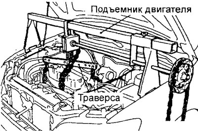
Engine 4G15.
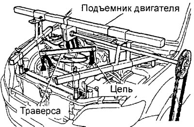
Engine 4G93.
d) Insert a wooden block between the jack support foot and the engine oil pan, lift the engine slightly to relieve the support from the engine weight.
d) Loosen the bracket mounting nuts and bolts and remove the engine mount assembly with the bracket.
7. Removing the engine assembly.
a) Check that all cables, wires (electrical connectors), hoses and other connections are disconnected from the engine.
b) Install special devices on the engine (engine lift and crossbar or any other similar tool).
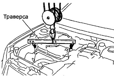
c) Using special tools, slowly lift the engine assembly up out of the engine compartment so that it does not move to the side.
Installation
Installation is carried out in the reverse order of removal.
When installing parts, please pay attention to the following operations:
1. Installing the engine assembly.
a) Using special tools (engine lift and crossbar), slowly lower and install the engine assembly into the engine compartment so that it does not move to the side.
b) Remove the special devices (engine lift and crossmember) from the engine.
c) When installing the engine, carefully check that the wires, tubes, hoses and wire connectors are connected correctly, that they are not pinched, twisted, damaged, etc.
2. Installing the engine support.
a) Place a hydraulic trolley jack under the engine (inserting a wooden block between the jack support foot and the engine oil pan) and install the engine support, adjusting the engine position using the jack.
b) Support the engine with a jack.
c) Supporting the engine with a special tool (jack), disconnect the hoist.
3. Installing the O-ring and flange of the high pressure fuel hose.
a) Apply a small amount of engine oil to the working edge of the O-ring around its entire circumference.
b) Rotate the flange of the high-pressure fuel hose to the right and left, carefully install the hose without damaging the O-ring. After connecting, check that the hose rotates smoothly.
c) If the hose flange does not rotate smoothly, the O-ring may be jammed. Disconnect the high-pressure fuel hose flange and check the O-ring for damage, then repeat the installation from step b.
d) Tighten the high pressure fuel hose flange mounting bolts to the specified torque.
Tightening torque: 5 ±1 Nm
4. Installing the lower and upper radiator hoses.
a) When connecting the radiator hose, push the hose onto the pipe until it stops against the protrusion of the pipe, then tighten the clamp.
b) The hose clamp should always be installed in the position in which the clamp was previously installed. Therefore, before installing the clamp, align the installation marks on the hose clamp and the radiator hose, then connect the hose.
After completing the installation of the parts, perform the following operations:
- a) Connect the exhaust pipe from the exhaust manifold.
- b) (Engine 4G15) Connect the accelerator pedal cable
- c) Install the battery tray and battery.
- d) Install the air filter.
- d) Install the hood.
- e) (Engine 4G93) Install the radiator.
- g) Fill with coolant and engine oil.
- c) Install the engine crankcase protective cover.
- i) Adjust the accelerator pedal cable.
- k) Check for fuel leaks.