



Contents: Removal ⤓ Examination ⤓ Repair ⤓ Repair dimensions of the piston and…⤓ Installation ⤓ Table. Selection of main bearing…⤓ Table. Selection of main bearing…⤓
Removal
The parts are removed in the order of numbers shown in the figure "Removing the crankshaft and torque converter drive plate".
Lay out the removed parts (thrust half rings and main bearing shells, etc.) in the order they correspond to the cylinder numbers.
Examination
Crankshaft
Caution: If the clearance between the crankshaft journals and the bearings is outside the permissible limits, replace the bearings and, if necessary, the crankshaft.
1. Checking the clearance in the crankshaft main bearings.
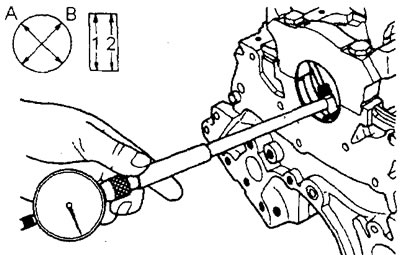
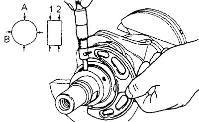
a) Measure the outside diameter of the crankshaft main journal and the inside diameter of the crankshaft main bearing shell in two mutually perpendicular directions (marked "A" and "B" in the figure) and in two sections along the length (marked "1" and "2" in the figure).
Nominal outside diameter of crankshaft main journal:
- Engine 4G15 - 48.00 mm
- Engine 4G93 - 50.00 mm
Main bearing clearance:
- nominal - 0.02-0.04 mm
- maximum permissible - 0.1 mm
b) If the clearance value exceeds the maximum permissible value, replace the main bearing shells and, if necessary, the crankshaft.
2. Determining the clearance size in the main bearings of the crankshaft using a plastic gauge.
Note: Using this method significantly simplifies the procedure for determining clearances in crankshaft bearings.
a) Clean the surfaces of the cylinder block and crankshaft bed, crankshaft main journals and bearing shells from oil deposits, grease and other contaminants.
b) Carefully place the crankshaft into the cylinder block.
c) Cut a piece of plastic calibration wire whose length matches the width of the journal, then place it on the crankshaft journal along the crankshaft axis.
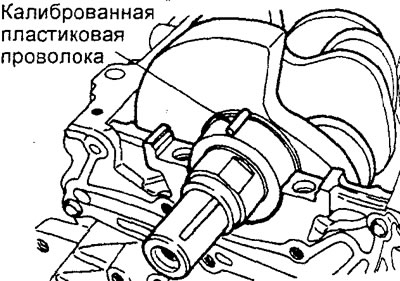
d) Carefully install the crankshaft bed onto the cylinder block and tighten the mounting bolts, but with the minimum tightening torque.
d) Unscrew the mounting bolts, carefully remove the bed from the shaft.
e) Measure the width of the crushed plastic gauge wire at its widest point using the scale printed on the plastic gauge package.
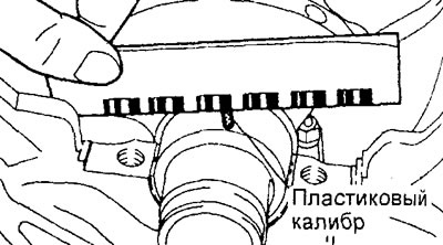
If the gauge is on the shaft journal
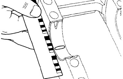
If the gauge is on the shaft bed.
3. Checking the out-of-roundness and taper of the main and connecting rod journals.
a) Check the out-of-roundness and taper of the main and connecting rod journals as shown in the figure.
Maximum permissible values:
- Out-of-roundness - no more than 0.005 mm
- Taper - no more than 0.01 mm

b) If the out-of-roundness or taper is greater than the maximum permissible value, replace the crankshaft.
Rear crankshaft oil seal
1. Check the crankshaft oil seal lip for wear or damage.
2. Check the rubber part of the seal for hardening or destruction.
3. Check the condition of the seal housing for cracks and damage.
Torque Converter Drive Plate
Check the torque converter drive plate for deformation, damage and cracks. Replace if necessary.
Cylinder block
1. Preparation for inspection after removing all parts.
a) Before cleaning the cylinder block, check for any signs of coolant leaks or any obvious damage.
b) Clean the parts from dirt, oil, carbon residues, scale and other types of deposits, after which you can begin inspection and repair operations.
c) Remove deposits from the oil holes and make sure that these holes are not clogged with dirt. If necessary, blow out the holes of the lubrication system and cooling system channels with compressed air.
d) All parts must be neatly laid out in accordance with the assembly order.
2. Assessment of the condition of the cylinder block.
a) Visually inspect the cylinder block for gasket residue or other foreign particles, damage, rust and corrosion. If any defects are found, repair them or replace the cylinder block.
b) Check the cylinder block with a liquid solution to determine if there are any cracks. If the defects are obvious, replace or repair the cylinder block.
3. Checking the warping of the cylinder block mating surface.
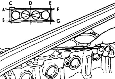
a) Using a straightedge and a flat feeler gauge, check the degree of warpage of the cylinder block working surfaces in the directions shown in the figure. The cylinder block surface must be cleaned of foreign particles.
Nominal value is 0.05mm or less
The maximum permissible value is 0.1 mm
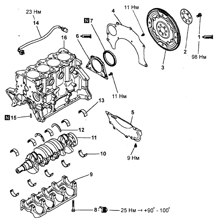
Removal the crankshaft and torque converter drive plate (4G93 engines). 1 - bolt; 2 - adapter plate; 3 - torque converter drive plate; 4 - rear plate of the cylinder block; 5 - protective cover of the gearbox housing; 6 - crankshaft rear oil seal housing; 7 - rear crankshaft oil seal; 8 - crankshaft bed mounting bolt; 9 - crankshaft bed; 10 - lower main bearing shell; 11 - crankshaft; 12 - upper thrust half rings; 13 - upper main bearing shell; 14 - knock sensor; 15 - oil nozzle; 16 - cylinder block.
b) If the warping is significant, correct the defect to an acceptable value or replace the cylinder block.
Maximum grinding depth - 0.20 mm
Attention: the total thickness of the metal removed from the cylinder head and cylinder block must not exceed 0.2 mm in total.
Height of cylinder block (new):
- Engines 4G15 - 256.0 mm
- Engines 4G93 - 263.5 mm
4. Checking the cylinder mirror.
Check the cylinder bore for scratches and signs of seizure (scoring). If defects are obvious, repair (bored) to the repair size or replace the cylinder block.
5. Checking the clearance between the piston (with connecting rod assembly) and the cylinder.
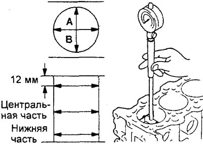
Using a bore gauge, measure the cylinder diameter and taper (deviation from cylindricity) of the cylinder. If there is severe wear, bore the cylinder to the repair size, replace the piston and piston rings as a set.
Take measurements in the places shown in the figure.
Nominal value:
Inner diameter of engine cylinder
- Engines 4G15 - 75.50 - 75.53 mm
- Engines 4G93 - 81.00 - 81.03 mm
- Maximum permissible taper (deviation from cylindricity) - 0.01 mm
Repair
Cylinder boring
Caution: Ream all four cylinders to the same oversize. Do not ream only one cylinder to the oversize.
1. Based on the largest diameter of the cylinder of the engine being repaired, obtained as a result of measurements, determine the repair size number of the pistons.
Please note: the piston repair size number is stamped on the piston bottom.
Repair dimensions of the piston and corresponding piston rings:
| Repair size | Label |
| No. 1 (+0.50 mm) | 0.50 |
| No. 2 (+1.00 mm) | 1.00 |
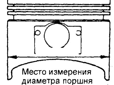
2. Measure the outside diameter of the piston to be used at the location shown in the figure.
3. Based on the measured value of the piston outside diameter, calculate the cylinder bore diameter.
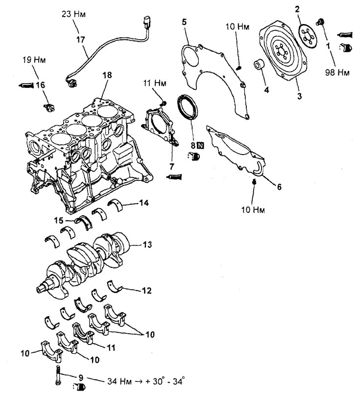
Removal the crankshaft and torque converter drive plate (4G15 engines). 1 - bolt; 2 - adapter plate; 3 - torque converter drive plate; 4 - crankshaft bushing; 5 - rear plate of the cylinder block; 6 - protective cover of the gearbox housing; 7 - crankshaft rear oil seal housing; 8 - rear crankshaft oil seal; 9 - crankshaft main bearing cap mounting bolt; 10 - crankshaft main bearing cap; 11 - cover No.3 of the crankshaft main bearing; 12 - lower main bearing shell; 13 - crankshaft; 14 - upper main bearing shell; 15 - main bearing shell No.3 (with iterated thrust half rings); 16 - Engine oil emergency pressure sensor; 17 - knock sensor; 18 - cylinder block.
Cylinder bore diameter = Piston outside diameter + (clearance between piston and cylinder) - 0.02 mm (honing allowance).
4. Bore all cylinders to the calculated diameter.
Attention: to prevent temperature deformations during boring, bore the cylinders in the following sequence: No.2, No.4, No.1, No.3.
5. Hone the cylinders to the final finished dimension (piston outside diameter + piston to cylinder clearance).
Attention: to prevent temperature deformations during boring, bore the cylinders in the following sequence: No.2, No.4, No.1, No.3.
6. Check the clearance between the piston and the cylinder.
The gap between the piston and the cylinder is 0.02 - 0.04 mm
Installation
Installation of parts is carried out in the reverse order of removal.
When installing the parts, please pay attention to the following operations.
Note: Apply engine oil to all moving and sliding parts before assembly and installation.
1. Selection of crankshaft main bearing shells.
Note: If the liner needs to be replaced, select and install the correct size liner.
a) If the crankshaft is supplied as a spare part, identify the color or symbol marks of the crankshaft main journals, which are stamped in the location shown in the figure. If identification of the crankshaft by marks is not possible (marks are missing), measure the diameter of each crankshaft main journal.
The material was created based on the website mitsubishiman
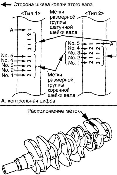
Crankshaft marks for 4G93 engine.
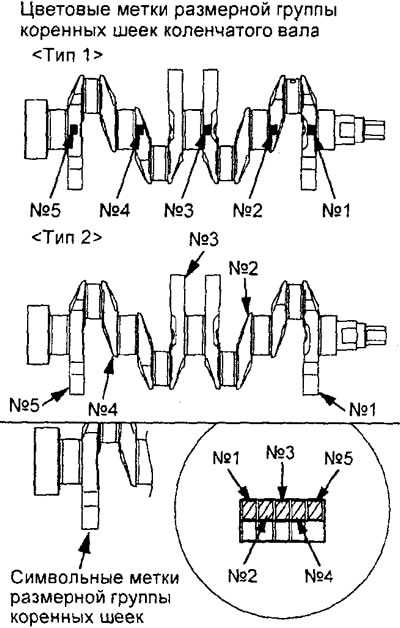
Crankshaft marks for 4G15 engine.
b) Determine the symbolic identification marks on the cylinder block (dimension groups of bore diameters for the main bearings), which are stamped in the place shown in the figure, in the direction from the front to the rear of the block. The mark for journal No.1 is located on the front side of the engine (on the timing belt side).
Note: For the 4G93 engine, see the figure "Symbol identification marks for selecting crankshaft main bearing shells for the 4G93 engine".
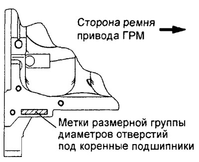
Symbolic identification marks for selection of main bearing shells for the 4G15 engine crankshaft.
c) The crankshaft main bearing shells are identified by color and/or symbol marks, which are located as shown in the figure.
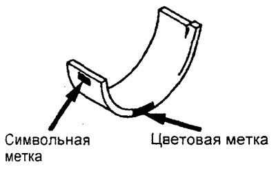
Engine 4G15.
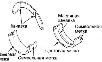
Engine 4G93.
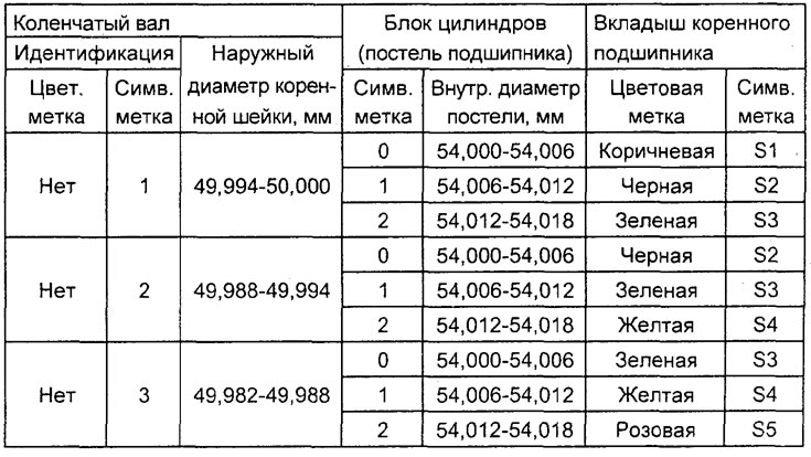
d) In accordance with the marks on the crankshaft (or the results of measuring the main journals of the shaft) and the identification marks on the cylinder block specified in paragraphs "a" - "c", select the correct main bearing shells according to the table provided.
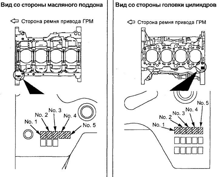
Symbolic identification marks for selection of main bearing shells for the 4G93 engine crankshaft.
Table. Selection of main bearing shells for the crankshaft of the 4G15 engine.
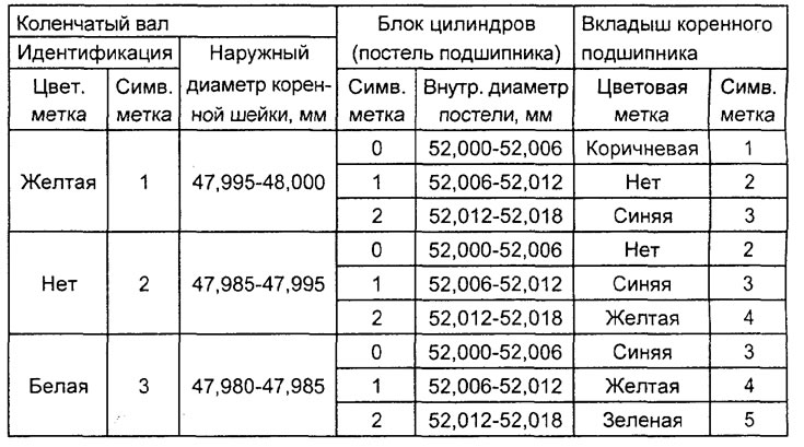
Table. Selection of main bearing shells for the crankshaft of the 4G93 engine.
2. Installing the crankshaft main bearing shells.
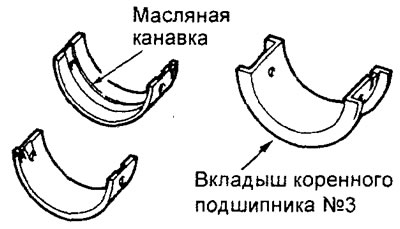
a) Install the upper main bearing shell (No. 1, 2, 4 and 5 for 4G15 engine) of the crankshaft into the cylinder block.
Note: The upper shell of the crankshaft main bearing has a groove for supplying lubricant.
b) Install the lower main bearing shell (No. 1, 2, 4 and 5 for the 4G15 engine) of the crankshaft into the crankshaft bed.
c) (Engine 4G15) Install the upper and lower main bearing shells No.3.
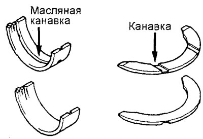
d) (Engine 4G93) Install thrust half rings on both sides of main bearing No.3 with the grooves facing outward (towards the counterweight cheek).
3. (Engine 4G15) Installing the crankshaft main bearing caps and mounting bolts.
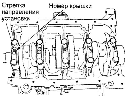
a) When installing, it is necessary to position the covers so that the arrows on the covers are directed towards the crankshaft pulley and the numbers on the covers correspond to the numbers on the shaft journals.
b) Apply engine oil to the bolt threads and under their heads.
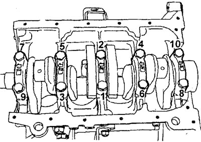
c) Tighten the main bearing cap bolts to the specified tightening torque in the sequence shown in the figure.
Tightening torque - 34 Nm
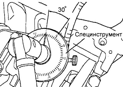
d) Tighten the main bearing cap mounting bolts by an angle of 30° in the sequence specified above.
Attention:
- If the bolt is turned at an angle less than 30°, the crankshaft bed will not be secured sufficiently.
- If the bolt is turned at an angle of more than 34°, then unscrew the bolt and repeat the tightening procedure from step "a".
d) Make sure the crankshaft rotates smoothly.
e) Check the crankshaft axial clearance as shown in the figure.
Crankshaft axial clearance:
- nominal - 0.05-0.18 mm
- maximum permissible - 0.25 mm
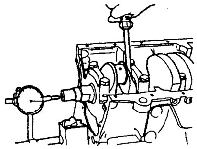
g) If the clearance value exceeds the maximum permissible value, replace the main bearing shells No.3.
4. (Engine 4G93) Installing the crankshaft bed and its mounting bolts.
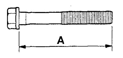
a) Before installing the fastening bolts, check that the length of the rod "A" for each bolt does not exceed the maximum permissible value. If the maximum value is exceeded, replace the bolt.
The maximum permissible value is no more than 71.1 mm
b) Install the crankshaft bed on the cylinder block so that the arrow on it is located on the timing belt side.
c) Apply engine oil to the bolt threads and under their heads.
d) Tighten the crankshaft bed mounting bolts to the specified tightening torque in the sequence shown in the figure.
Tightening torque - 25 Nm
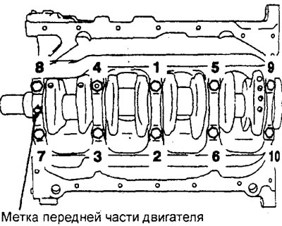
d) Tighten the crankshaft bed (bearing cover) mounting bolts by an angle of 90° (1/4 turn) in the sequence specified above.
Attention:
- If the bolt is turned at an angle less than 90°, the crankshaft bed will not be secured sufficiently.
- If the bolt is turned to an angle of 100°, then unscrew the bolt and repeat the tightening procedure from step "a".
e) Make sure the crankshaft rotates smoothly.
g) Check the crankshaft axial clearance as shown in the figure.
Crankshaft axial clearance:
- nominal - 0.05-0.25 mm
- maximum permissible - 0.40 mm
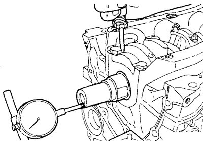
h) If the gap size exceeds the maximum permissible value, replace the thrust half rings.
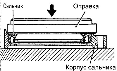
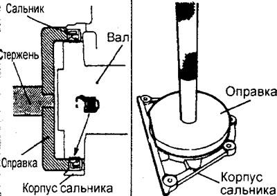
5. Installing the rear crankshaft oil seal.
Using a special mandrel, install the new oil seal into the oil seal housing as shown in the figure.
Engine 4G15
Engine 4G93
6. Installing the crankshaft rear oil seal housing.
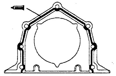
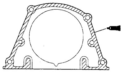
a) Apply the specified sealant to the oil seal housing in the places shown in the figure.
Sealant MITSUBISHI GENUINE Part # MD 970389, Three Bond No.1207F or equivalent
Engine 4G15
Engine 4G93
b) Apply a small amount of engine oil to the working lip of the oil seal around its entire circumference and install the oil seal housing on the cylinder block.
Tightening torque - 11 Nm
Note:
- Install the seal housing within 15 minutes after applying the sealant.
- After installation, do not allow oil or coolant to come into contact with the sealant-coated surfaces of the seal housing.
7. Installing the torque converter drive plate.
See the relevant section item "Replacing oil seals" chapters "Engines - mechanical part".