



Disassembly
The main preliminary operations that need to be taken into account are given in the sections "Replacing oil seals" and "Replacing the cylinder head gasket" chapters "GDI engines - mechanical part".
The parts are removed in the order of numbers shown in the figure "Removing the rocker arms and camshafts".
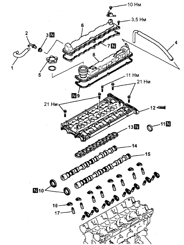
Removal rocker arms and camshafts (4G93-GDI engine). 1 - forced crankcase ventilation hose, 2 - forced crankcase ventilation valve, 3 - forced crankcase ventilation valve gasket, 4 - ventilation hose, 5 - oil filler cap, 6 - cylinder head intake valve cover, 7 - cylinder head intake valve cover gasket, 8 - cylinder head exhaust valve cover, 9 - gasket exhaust valve cover cover cylinder head, 10 - camshaft oil seal, 11 - round plug, 12 - block of camshaft bearing caps, 13 - gasket block of camshaft caps, 14 - camshaft inlet valves, 15 - camshaft exhaust valves, 16 - rocker arm, 17 - hydrocompensator.
When removing parts, pay attention to the operation of removing the camshaft bearing cap block.
Gradually, in 2-3 steps, unscrew the bolts securing the camshaft bearing cap block.
Examination
Checking the camshaft
Each camshaft is checked in the same way as the corresponding check for MPI engines (see section "Rocker Arms and Camshaft (MPI Engine)").
Below are the technical data for GDI engines required for testing.
Nominal diameter of bearing journals:
- Engine 4G15 - 25.95 - 25.97 mm
- Engine 4G93 - 26.0 mm
Maximum permissible oil clearance (between each bearing journal and bearing) — 0.05 - 0.09 mm
Height of cams:
Engine 4G15:
| Cam | Nomin. | Limit. |
| Inlet | 34.85 mm | 34.35 mm |
| Outlet | 34.59 mm | 34.09 mm |
Engine 4G93:
| Cam | Nomin. | Limit. |
| Inlet | 35.49 mm | 34.99 mm |
| Outlet | 34.73 mm | 34.23 mm |
Camshaft runout:
- Nominal value less than - 0.02 mm
- The maximum permissible value is 0.10 mm
The original article is on [MitsubishiMan.ru]
Checking the valve rocker arms
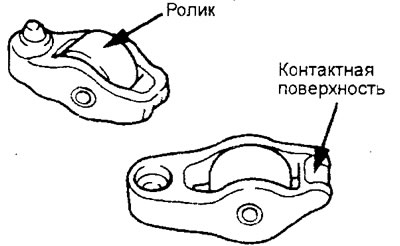
1. Check the surface of the valve rocker roller, replace the rocker arm if there is local wear, damage, or scoring.
2. Check the roller rotation and replace the valve rocker arm if present; jamming or increased play.
3. Check the condition of the rocker arm tappet surface (the point of contact with the end of the valve stem) for damage or scoring. Replace the rocker arm if significant wear is detected.
Checking the tightness and cleaning hydraulic compensators
Attention:
- The hydraulic compensator is a precision part. Do not allow dust, dirt or other foreign particles to enter it.
- Do not disassemble the hydraulic compensator.
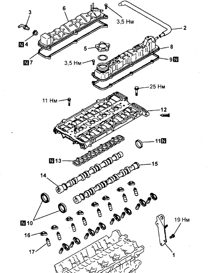
Removal rocker arms and camshafts (4G15-GDI engine). 1 - engine suspension bracket, 2 - ventilation hose, 3 - forced crankcase ventilation valve, 4 - bushing, 5 - oil filler cap, 6 - intake valve cover cylinder head, 7 - gasket intake valve cover cylinder head, 8 - exhaust valve cover cylinder head, 9 - gasket exhaust valve cover cover cylinder head, 10 - camshaft oil seal, 11 - round plug, 12 - block of camshaft bearing caps, 13 - gasket block of camshaft covers, 14 - camshaft inlet valves, 15 g camshaft exhaust valves, 16 - rocker arm, 17 - hydrocompensator.
- When flushing the hydraulic compensator, use only clean diesel fuel.
1. Prepare three containers ("A", "B" and "C") with a sufficient amount of clean diesel fuel (approximately 5 liters) to completely immerse the hydraulic compensator, located vertically.
2. Place the hydraulic compensator in container "A" and clean it from the outside. If the deposits are difficult to remove, use a nylon brush.
3. Cleaning the internal cavities of the hydraulic compensator.
a) Immerse the hydraulic compensator in container "B" as shown in the figure.
b) Lightly pressing down the steel inner ball of the hydraulic compensator with a special rod, simultaneously move the plunger up and down (5-10 times) until the plunger begins to move smoothly. This will eliminate the plunger hanging and remove contaminated oil.
Note: The steel ball spring is weak, so the performance of the hydraulic compensator may be impaired if strong pressure is applied to the rod when removing air.
Note: If the plunger remains stationary or another malfunction of the mechanism is detected, replace the hydraulic compensator.
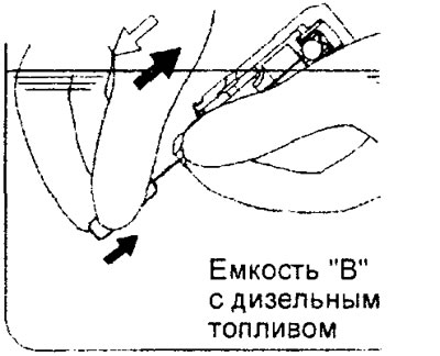
c) Remove the hydraulic compensator from the container, then press the steel ball lightly so that the plunger pushes the diesel fuel out of the high pressure chamber.
Caution: Make sure that the oil hole in the hydraulic compensator housing is directed towards container "B".
d) Repeat steps "a" - "c" again to complete the flushing.
4. Removing air from the hydraulic compensator.
a) Immerse the hydraulic compensator into container "C" with the plunger facing up.
b) While lightly pressing down the steel inner ball of the hydraulic compensator with a special rod, simultaneously move the plunger up and down (four to five times) to remove air until the plunger begins to move smoothly.
Note: Using special devices (stoppers) to compress the hydraulic compensator facilitates the process of removing air.
Note: The steel ball spring is weak, so the performance of the hydraulic compensator may be impaired if strong pressure is applied to the rod when removing air.
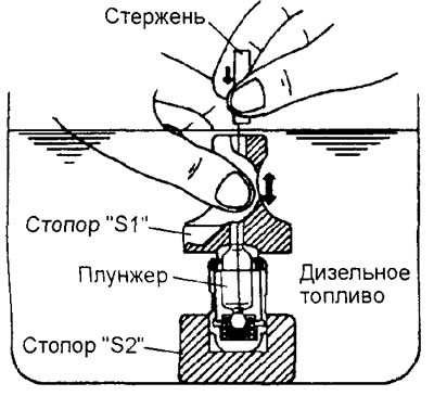
c) Remove the special tool from the hydraulic compensator. Press the plunger. If it is difficult to move the plunger, the hydraulic compensator is in normal condition. If the plunger moves freely, the air bleeding operation must be repeated. If the plunger still moves freely, replace the hydraulic compensator.
Caution: After completing the air bleeding operation, install the hydraulic compensator vertically upward to prevent diesel fuel from leaking out.
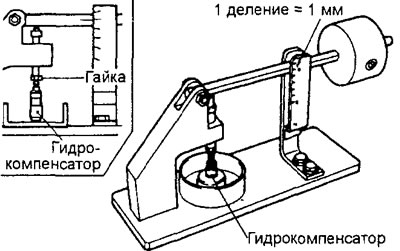
5. After performing the air removal operation, install the hydraulic compensator in a special device (a stand for testing the tightness of the hydraulic compensator).
Note: When installing the hydraulic compensator on the test bench, use the bench adjusting nut to adjust the device to the height of the hydraulic compensator, as shown in the figure.
6. After the hydraulic compensator plunger has dropped by approximately 0.2-0.5 mm, measure the time it takes for the plunger to drop by 1 mm. Replace the hydraulic compensator if the measured time does not correspond to the nominal value.
Nominal value - 4-20 sec. (At diesel fuel temperature of 15-20°C)
Assembly
Installation of parts is carried out in the reverse order of removal.
Caution: Apply engine oil to all moving parts during assembly.
When installing parts, please pay attention to the following operations:
1. Installation of hydraulic compensators.
a) If hydraulic lifters are reused, clean them (see paragraph "Checking the tightness and cleaning hydraulic compensators").
b) Remove air from the hydraulic lifters (see paragraph "Checking the tightness and cleaning hydraulic compensators").
c) Install hydraulic compensators in the cylinder head, preventing diesel fuel from leaking out of the hydraulic compensators.
d) Install the valve rocker arm in place so that it rests against the hydraulic compensator.
2. Installing camshafts.
a) Check that each valve rocker arm is located on one side on the hydraulic compensator and on the other side on the end of the valve stem.
b) Lubricate the camshaft cams and bearing journals with clean engine oil.
c) Install the intake and exhaust camshafts into the cylinder head.
Caution: do not mix up the camshafts - there is a hole on the end of the rear part of the exhaust camshaft for the camshaft position sensor rotor mounting bolt.
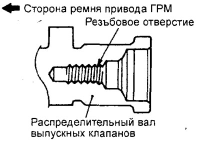
d) Turn the crankshaft so that the piston of the first cylinder is at top dead center (TDC).
d) Position the camshafts in the cylinder head so that their guide pins are in the position shown in the figure.
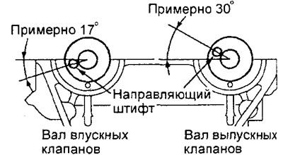
Engine 4G15.
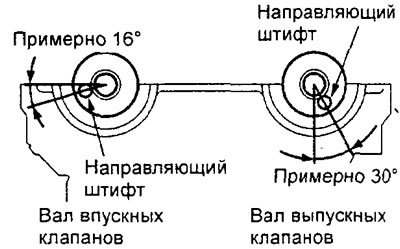
Engine 4G93.
3. Installing the camshaft bearing cap block.
a) Before installation, make sure that the camshafts are correctly positioned in the cylinder head.
b) Clean the mating surfaces of the cylinder head and the camshaft bearing cap block from the remains of the old sealant. After cleaning, degrease the surfaces for applying the sealant.
Caution: Do not allow any old sealant residue to enter the engine.
c) Apply the specified sealant in a continuous bead approximately 3 mm in diameter to the bottom of the camshaft bearing cap block (into the groove) in the locations shown in the figure.
Sealant - ЗМ ATD Part # 8660, Three Bond 1207F or equivalent
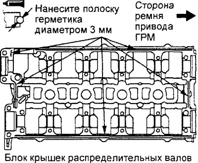
Engine 4G15.
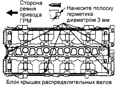
Engine 4G93.
d) Apply the specified sealant in a continuous bead approximately 3 mm in diameter to the mating surface of the cylinder head at the locations shown in the figure.
Sealant - ЗМ ATD Part # 8660, Three Bond 1207F or equivalent
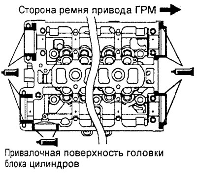
Engine 4G15.
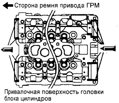
Engine 4G93.
d) Install the camshaft bearing cap block gasket onto the cylinder head.
e) Install the camshaft bearing cap assembly onto the cylinder head before the sealant hardens (dries),
g) Gradually tighten the camshaft cap block mounting bolts in two or three stages in the order shown in the figure. Tighten the bearing cap block mounting bolts to the specified torque during the final tightening sequence.
Tightening torque:
- bolt M6 - 10-12 Nm
- bolt M8
- Engine 4G15 - 24-26 Nm
- Engine 4G93 - 19-23 Nm
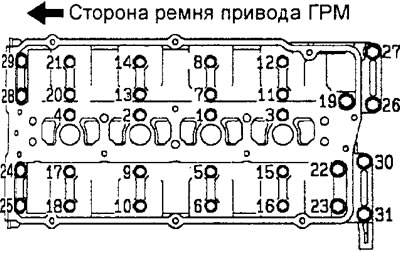
Engine 4G15.
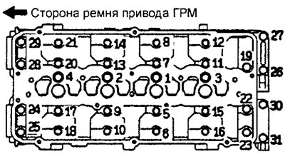
Engine 4G93.
c) Apply engine oil to the working edge of the camshaft oil seal.
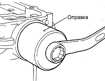
i) Using a special tool, press in the camshaft seals before the sealant hardens.
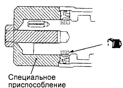
j) Remove any excess squeezed out sealant from around the periphery of the camshaft bearing cap assembly before it hardens.