



Contents: Replacing the camshaft seal ⤓ Replacing the front crankshaft oil…⤓ Replacing the rear crankshaft oil…⤓
Replacing the camshaft seal
Before you begin removing parts, perform the following operations:
- a) Release residual pressure from the high-pressure line (see chapter "Fuel injection system (GDI)").
- b) Remove the engine crankcase protective cover.
- c) Drain the coolant and engine oil.
- d) Remove the air filter.
- d) Remove the battery and battery tray.
The parts are removed in the order of numbers shown in the figure "Replacing the camshaft oil seal".
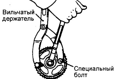
When removing parts, pay attention to the operation of removing the camshaft pulley.
Secure the camshaft pulley from turning using a special fork holder and special bolts.
Installation is carried out in the reverse order of removal.
When installing parts, please pay attention to the following operations:
1. Installation of hydraulic compensators.
Caution: If hydraulic lifters are reused, it is recommended to check them and clean them if necessary (see the relevant procedures in the section "Rocker arms and camshafts" chapters "Engine - General Repair Procedures"), then carefully install it into the cylinder head.
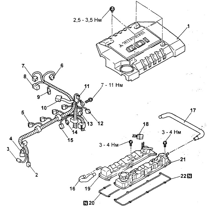
Replacing the camshaft oil seal (engine 4G15). 1 - decorative engine cover; 2 - connector of the electromagnetic clutch of the air conditioning compressor; 3 - connector of the sensor-switch for the fluid pressure in the hydraulic system of the power steering; 4 - crankshaft position sensor connector; 5 - ignition coil connector; 6 - throttle position sensor connector; 7 - throttle servo connector; 8 - EGR valve servo connector; 9 - connector of the electromagnetic valve of the adsorber purge; 10 - Engine management system and injector wiring harness connector; 11 - Noise suppression capacitor connector; 12 - oxygen sensor connector; 13 - camshaft position sensor connector; 14 - coolant temperature sensor connector; 15 - knock sensor connector; 16 - forced crankcase ventilation hose; 17 - ventilation hose (remove ignition coils; intake manifold and timing belt); 18 - intermediate connector of injectors; 19 - cylinder head intake valve cover; 20 - cylinder head intake valve cover gasket; 21 - cylinder head exhaust valve cover; 22 - cylinder head exhaust valve cover gasket.
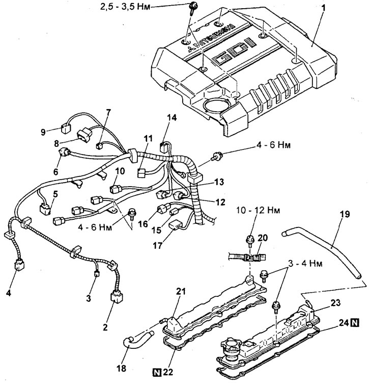
Replacing the camshaft oil seal (engine 4G93). 1 - decorative engine cover; 2 - connector of the electromagnetic clutch of the air conditioning compressor; 3 - connector of the sensor-switch for the fluid pressure in the hydraulic system of the power steering; 4 - crankshaft position sensor connector; 5 - fuel pressure sensor; 6 - EGR valve servo connector; 7 - connector of the electromagnetic valve of the adsorber purge; 8 - throttle position sensor connector; 9 - throttle servo connector; 10 - ignition coil connector; 11 - Engine management system and injector wiring harness connector; 12 - oxygen sensor connector; 13 - camshaft position sensor connector; 14 - Noise suppression capacitor connector; 15 - coolant temperature gauge sensor connector; 16 - coolant temperature sensor connector; 17 - knock sensor connector; 18 - forced crankcase ventilation hose; 19 - ventilation hose (remove ignition coils; intake manifold and timing belt); 20 - intermediate connector of injectors; 21 - cylinder head intake valve cover; 22 - Cylinder head intake valve cover gasket; 23 - cylinder head exhaust valve cover; 24 - cylinder head exhaust valve cover gasket.
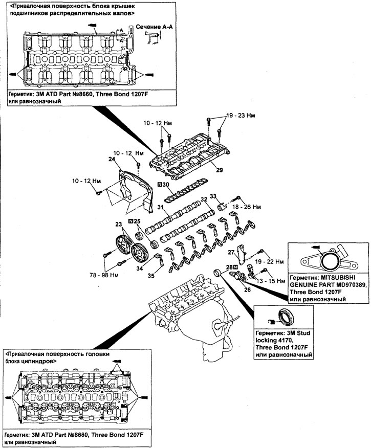
Replacing the camshaft seal (engine 4G15); continuation). 23 - camshaft pulley; 24 - rear timing belt cover (upper); 25 - camshaft oil seal; 26 - camshaft position sensor bracket; 27 - Engine mount bracket; 28 - round plug (remove the fuel injection pump); 29 - camshaft bearing cap block; 30 - camshaft bearing cap block gasket; 31 - intake camshaft; 32 - exhaust camshaft; 33 - camshaft position sensor rotor; 34 - rocker arm; 35 - hydraulic compensator.
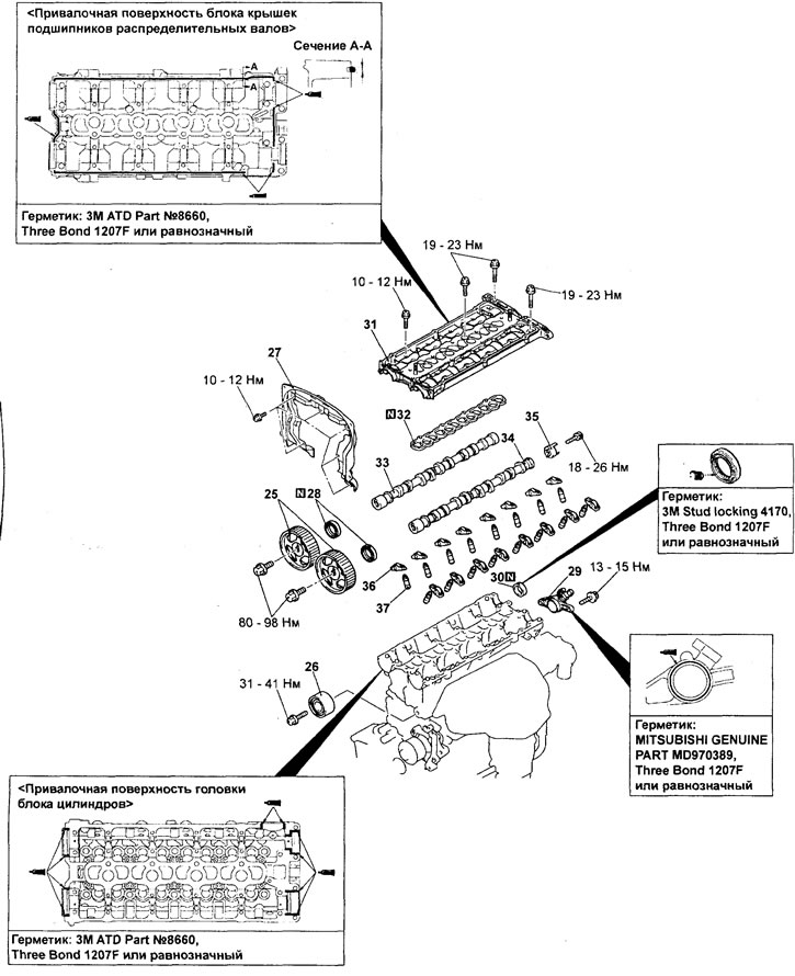
Replacing the camshaft oil seal (engine 4G93); continuation). 25 - camshaft pulley; 26 - guide roller; 27 - rear timing belt cover (upper); 28 - camshaft oil seal; 29 - camshaft position sensor bracket; 30 - round plug (remove the fuel injection pump); 31 - camshaft bearing cap block; 32 - camshaft bearing cap block gasket; 33 - intake camshaft; 34 - exhaust camshaft; 35 - camshaft position sensor rotor; 36 - rocker arm; 37 - hydraulic compensator.
2. Installing camshafts
a) Apply a small amount of engine oil to the camshaft cams and bearing journals.
b) Install the camshafts into the cylinder head.
Caution: Do not mix up the camshafts. There is a hole on the end of the rear part of the exhaust camshaft for the camshaft position sensor rotor mounting bolt.
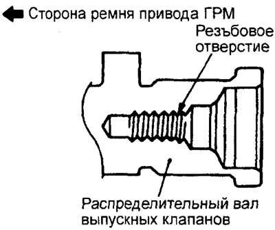
c) Position the camshafts in the cylinder head so that their guide pins are in the position shown in the figure.
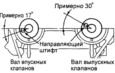
Engine 4G15.
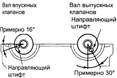
Engine 4G93.
3. Installing the camshaft bearing cap block (if removed).
a) Apply the specified sealant in a continuous bead approximately 3 mm in diameter to the bottom of the camshaft bearing cap block (into the groove) at the locations shown in the figure.
Sealant - Mitsubishi Genuine Part # MD970389, Three Bond 1207F or equivalent
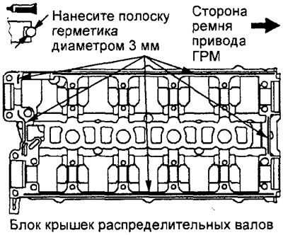
Engine 4G15.
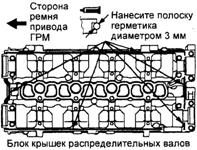
Engine 4G93.
b) Apply the specified sealant in a continuous bead approximately 3 mm in diameter to the mating surface of the cylinder head at the locations shown in the figure.
Sealant - Mitsubishi Genuine Part # MD970389, Three Bond 1207F or equivalent
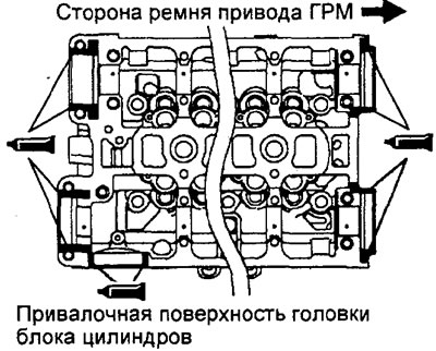
Engine 4G15.
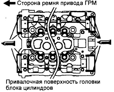
Engine 4G93.
c) Install the camshaft bearing cap block gasket.
d) Install the camshaft bearing cap assembly onto the cylinder head before the sealant dries and hardens.
d) Install the camshaft bearing cap block mounting bolts and gradually tighten the bolts in two or three stages in the order shown in the figure. Tighten the bolts to the specified torque during the final tightening sequence.
Tightening torque:
Engine 4G15:
- A (bolt M6x32) - 10-12 Nm
- B (bolt M6x35) — 10-12 Nm
- C (bolt M8x40) — 19-23 Nm
- D (bolt M8x40) - 19-23 Nm
Engine 4G93GDI:
- A (bolt M8x32) — 19-23 Nm
- B (bolt M6x35) — 10-12 Nm
- C (bolt M8x40) — 19-23 Nm
- D (bolt M8x40) - 19-23 Nm
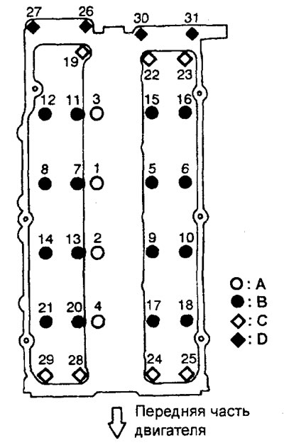
Engine 4G15.
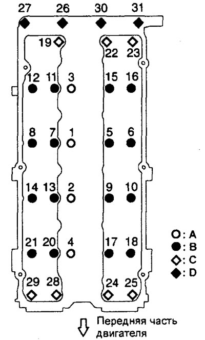
Engine 4G93.
4. Installing the round plug.
Using a special tool (mandrel), install the round plug as shown in the figure.
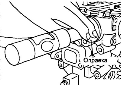
5. Installing the camshaft oil seal.
a) Apply a small amount of engine oil to the working lip of the oil seal around its entire circumference.
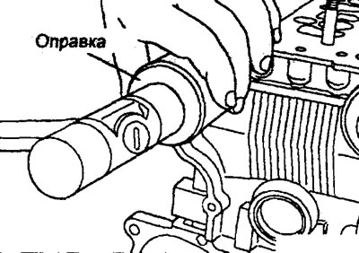
b) Using a special mandrel, press in the oil seal as shown in the figure.
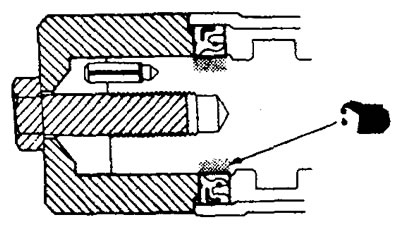
6. Installing the camshaft pulley.
Using a special device, secure the camshaft pulley from turning in the same way as the removal procedure, and tighten the pulley mounting bolt to the specified torque.
Tightening torque: 88+10 Nm
7. Installing the decorative engine cover.
a) Pre-tighten the casing mounting bolts in the sequence shown in the figure so that the casing can be moved by hand.
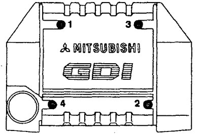
Engine 4G15.
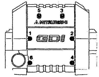
Engine 4G93.
b) Finally tighten the casing mounting bolts to the specified torque in the sequence shown in the figure.
Tightening torque: 3 Nm
Installation is carried out in the reverse order of removal.
After completing the installation of the parts, perform the following operations:
- a) Adjust the tension of the drive belts of the attachments (see the relevant section of the chapter "Maintenance and general check and adjustment procedures").
- b) Install the battery tray and battery.
- c) Install the air filter.
- d) Fill with coolant and engine oil.
- d) Perform the procedure for bleeding air from the high-pressure fuel line (see the corresponding procedure when installing the injection pump in the chapter "Fuel injection system (GDI)").
- e) Check for fuel leaks.
- g) Install the engine crankcase protective cover.
Replacing the front crankshaft oil seal
Before you begin removing parts, perform the following operations:
a) Remove the timing belt.
b) Remove the crankshaft position sensor.
The parts are removed in the order of numbers shown in the figure "Removing the crankshaft oil seals".
When removing parts, pay attention to the operation of removing the oil seal.
a) Cut off part of the working edge of the crankshaft oil seal.
b) Wrap the tip of the screwdriver in a cloth, insert it into the cut in the seal and remove the seal.
Caution: Be careful not to damage the crankshaft and oil pump housing.
Installation of parts is carried out in the reverse order of removal.
When installing parts, please pay attention to the following operations:
1. Installing the seal.
a) Apply a small amount of engine oil to the working lip of the oil seal around its entire circumference.
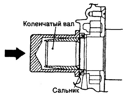
b) Tap the mandrel to install the seal so that it is flush with the seal body.
2. Installing the crankshaft toothed pulley.
a) Clean and then degrease the following surfaces and parts: oil pump housing face, crankshaft surface, spacer, sensor rotor and toothed pulley.
Note: Degreasing is necessary to improve the mating of parts.
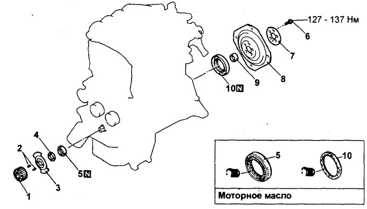
Removal crankshaft oil seals (engine 4G15). 1 - toothed pulley of the crankshaft; 2 - key; 3 - crankshaft position sensor rotor; 4 - washer; 5 - front crankshaft oil seal; 6 - torque converter drive plate mounting bolt; 7 - adapter plate; 8 - torque converter drive plate; 9 - crankshaft bushing; 10 - rear crankshaft oil seal.
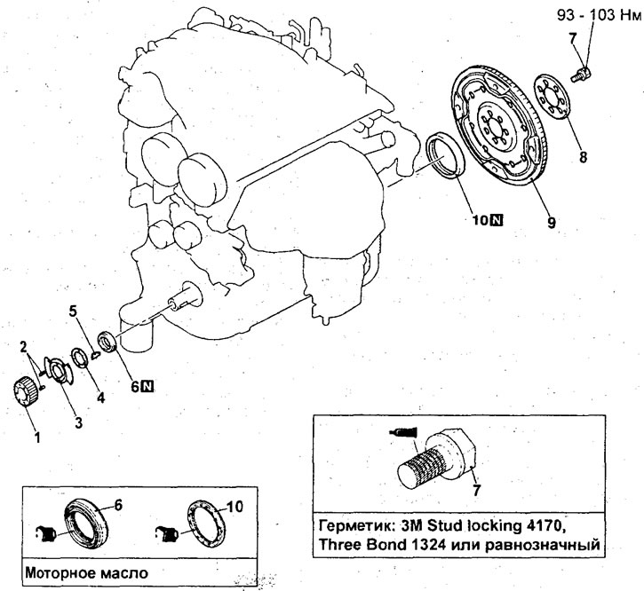
Removal crankshaft oil seals (engine 4G93). 1 - toothed pulley of the crankshaft; 2 - key; 3 - crankshaft position sensor rotor; 4 - washer; 5 - key; 6 - front crankshaft oil seal; 7- torque converter drive plate mounting bolt; 8 - adapter plate; 9 - torque converter drive plate; 10 - rear crankshaft oil seal.
b) Clean the surface of the crankshaft toothed pulley that contacts the shaft.
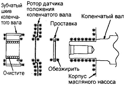
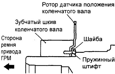
c) Install the washer, crankshaft position sensor rotor and crankshaft toothed pulley, aligning the mounting holes with the spring pin as shown in the figure.
After completing the installation of the parts, perform the following operations:
a) Install the crankshaft position sensor.
b) Install the timing belt.
Replacing the rear crankshaft oil seal
Before you begin removing parts, perform the following operations:
- a) (2WD models) Remove the gearbox.
- b) (4WD models) Remove the transmission assembly with the transfer case.
The parts are removed in the order of numbers shown in the figure "Removing the crankshaft oil seals".
When removing parts, pay attention to the following operations:
1. Removing the torque converter drive plate.
Using a special tool, secure the torque converter drive plate, then unscrew the mounting bolts.
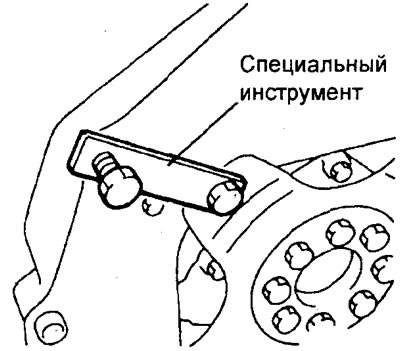
Engine 4G15.
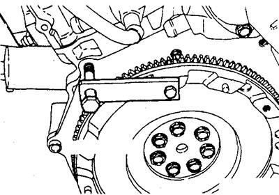
Engine 4G93.
2. Removing the oil seal.
a) Cut off part of the working edge of the crankshaft oil seal.
b) Wrap the tip of the screwdriver in a cloth, insert it into the cut in the seal and remove the seal.
Caution: Be careful not to damage the crankshaft and oil pump housing.
Installation of parts is carried out in the reverse order of removal.
1. Installing a new oil seal.
a) Apply a small amount of engine oil to the working lip of the oil seal around its entire circumference.
b) By tapping on the mandrel, install the seal so that its end surface is located at the level of the chamfer of the seal housing, as shown in the figure.
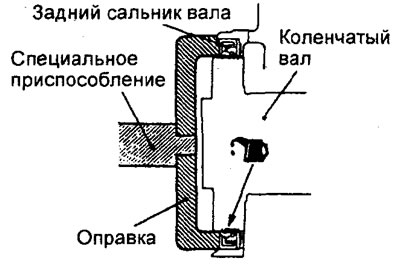
2. Installing the torque converter drive plate.
a) Before installation, clean the mounting bolts, threaded holes in the crankshaft and torque converter drive plate from oil, old sealant and other contaminants.
b) Lubricate the bearing surfaces of the washers of the torque converter drive plate mounting bolts with engine oil.
c) Apply engine oil to the threaded holes of the crankshaft.
d) Apply the specified sealant to the threads of the mounting bolt holes or to the bolt threads.
Sealant - ЗМ Stud Locking №4171, Three Bond 1324 or equivalent
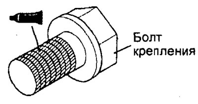
d) Using a special tool, fix the torque converter drive plate in the same manner as the removal procedure, then tighten the mounting bolts to the rated tightening torque.
Tightening torque:
- Engine 4G15 — 127-137 Nm
- Engine 4G93 93 — 103 Nm
After completing the installation of the parts, perform the following operations.
a) (4WD models) Install the transmission and transfer case assembly.
b) (2WD models) Install the gearbox.