
Removing
Perform the following operations before beginning to remove parts.
A) Remove the decorative engine cover.
b) Release residual pressure from the high pressure line (see chapter "fuel injection system (GDI)").
V) Remove the engine crankcase guard.
G) Drain the coolant.
d) Remove the air filter.
e) Remove the battery and battery tray.
and) Remove the hood.
h) Disconnect the exhaust pipe from the exhaust manifold.
Removal of parts is carried out in the order of the numbers indicated in the figure ("Removing the engine assembly".)
When removing parts, pay attention to the following operations:
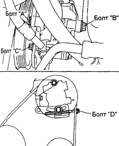
1. (Engine 4G15) Removing the belt 1 for the drive of the power steering pump and the air conditioning compressor.
A) Loosen the bolts "A", "IN" And "WITH" power steering pump.
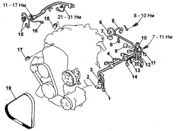
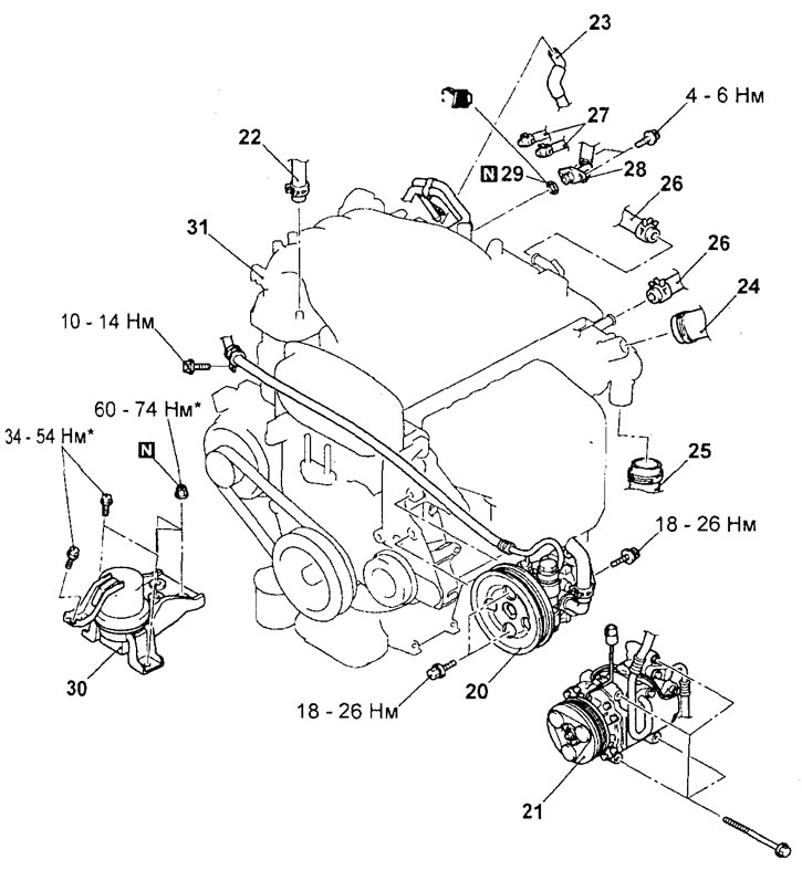
Removing the engine assembly (4G15 engine). 1 - air conditioning compressor electromagnetic clutch connector, 2 - power steering fluid pressure switch connector, 3 - crankshaft position sensor connector, 4 - ignition coil connector, 5 - throttle position sensor connector, 6 - throttle servo connector dampers, 7 - EGR valve servo connector, 8 - canister purge solenoid valve connector, 9 - engine management and injector wiring harness connector, 10 - interference suppression capacitor connector, 11 - oxygen sensor connector, 12 - camshaft position sensor connector, 13 - coolant temperature sensor connector, 14 - knock sensor connector, 15 - alternator connectors, 16 - emergency engine oil pressure sensor connector, 17 - brake booster vacuum hose connection, 18 - EVAP vacuum hose connection, 19 - pump drive belt power steering and air conditioning compressor.
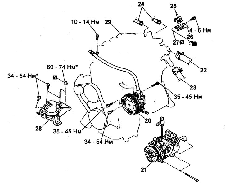
Removing the engine assembly (4G15 engine, continued). 20 - power steering pump, 21 - air conditioning compressor, 22 - upper radiator hose connection, 23 - lower radiator hose connection, 24 - heater hose connection, 25 - fuel return hose connection, 26 - fuel inlet hose connection, 27 - O-ring (remove the gearbox (2WD models) or gearbox and transfer case (4WD models), 28 - engine support assembly, 29 - engine assembly.
Note: the connections marked with the symbol should first be tightened only in advance, and the final tightening with the specified torque should be made after the engine is completely lowered onto the supports.
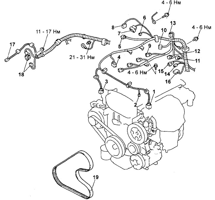
Removing the engine assembly (4G93 engine). 1 - connector for the electromagnetic clutch of the air conditioning compressor, 2 - connector for the sensor-switch for fluid pressure in the hydraulic system of the power steering, 3 - connector for the crankshaft position sensor, 4 - fuel pressure sensor, 5 - connector for the EGR valve servo drive, 6 - solenoid valve connector canister purge, 7 - throttle position sensor connector, 8 - throttle servo connector, 9 - ignition coil connector, 10 - engine management system wiring harness connector and injector intermediate connector, 11 - oxygen sensor connector, 12 - camshaft position sensor connector, 13 - interference suppression capacitor connector, 14 - coolant temperature indicator sensor connector, 15 - coolant temperature sensor connector, 16 - knock sensor connector, 17 - engine oil emergency pressure sensor connector, 18 - alternator connectors, 19 - power steering pump drive belt steering and air conditioning compressor.
b) Loosen the adjusting bolt "D" to relieve belt tension, then remove the belt.
Attention: in case of reuse of the drive belt of the power steering pump and air conditioning compressor, it is necessary to chalk on the back (non-working) belt surface an arrow indicating the direction of rotation (clockwise).
2. (Engine 4G93) Removing the drive belt for the power steering pump and air conditioning compressor.
A) Loosen the lock nut of the belt tensioner pulley for the power steering pump and air conditioning compressor.
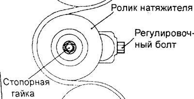
b) Loosen the adjusting bolt to release the belt tension, then remove the belt.
Attention: in case of reuse of the drive belt of the power steering pump and air conditioning compressor, it is necessary to chalk on the back (non-working) belt surface an arrow indicating the direction of rotation (clockwise).
3. Removing the power steering pump.
Remove the power steering pump from the engine along with the hoses connected to it.
Note: After removal, secure the power steering pump with hoses with wire in a place where it will not be obstructed or damaged when removing and installing the engine assembly.
4. Removing the air conditioning compressor.
Disconnect the A/C compressor wire connector and remove the compressor from its bracket along with the connected hoses.
Note: after removal, use a wire to hang the A/C compressor assembly together with the hose» on the body in a place where they will not interfere with the removal and installation of the engine assembly.
5. Removing the upper and lower radiator hose.
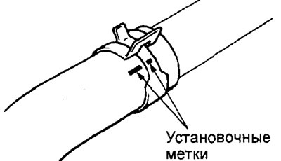
Before disconnecting the upper and lower radiator hoses, mark the relative position on the hose and hose clamps.
6. Removing the engine mount.
A) Place a rolling hydraulic jack under the engine.
b) Remove the special tools used to remove the gearbox.
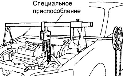
V) Fasten the motor to the yoke and hang it from a hoist or similar device (special device).
G) Insert a piece of wood between the jack foot and the engine oil pan, raise the engine slightly to relieve the weight of the engine support,
d) Loosen the nuts and bolts of the bracket and remove the engine support assembly with the bracket.
7. Removing the engine assembly.
A) Check that all cables, wires are disconnected from the engine (electrical connectors), hoses and other connections.
b) Install special tools on the engine (engine hoist and traverse or any other similar tool).
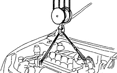
V) Using the special tools, slowly lift the engine assembly up from the engine compartment so that it does not move to the side.
Removing the engine assembly (4G93 engine, continued).20 - power steering pump, 21 - A/C compressor, 22 - brake booster vacuum hose connection, 23 - EVAP vacuum hose connection, 24 - upper radiator hose connection, 25 - lower radiator hose connection, 26 - hose connection heater, 27 - fuel return hose connection, 28 - fuel inlet hose connection, 29 - O-ring (remove the gearbox (2WD models) or gearbox and transfer box (4WD models)), 30 - engine support assembly, 31 - engine assembly.
Installation is made in an order, the return to removal.
When installing parts, pay attention to the following operations:
Complete engine installation.
A) With the help of special devices (engine lift and traverse) slowly lower and install the engine assembly in the engine compartment so that it does not move to the side.
b) Remove the special tools from the engine (engine lift and traverse).
V) When installing the engine, carefully check that the wires, tubes, hoses and wire connectors are connected correctly, that they are not pinched, twisted, damaged, etc.
Installing the engine mount.
A) Place a hydraulic jack under the engine (by inserting a block of wood between the jack foot and the engine oil pan) and install the engine support by adjusting the position of the engine with a jack
b) Support the engine with a jack
V) Supporting the engine with a special tool (jack), disconnect the hoist.
3. Install O-ring and fuel inlet hose.
A) Apply a small amount of clean engine oil to the fuel inlet hose O-ring.
Attention: do not allow engine oil to get inside the injection pump.
b) Be careful not to damage the o-ring when installing. Turning the fuel hose flange from side to side, connect it to the injection pump. After connecting, check that the flange turns freely without binding.
V) If the fuel hose flange does not turn smoothly, the O-ring may be pinched. In this case, disconnect the fuel hose, check the condition of the gasket, replace it if necessary. Reconnect the fuel hose and check again for smooth rotation of the flange.
G) Tighten the hose mounting bolts to the specified torque.
Tightening torque - 5± 1 Nm
4. Installing the fuel return hose. Install the fuel return hose with the identification mark facing as shown.
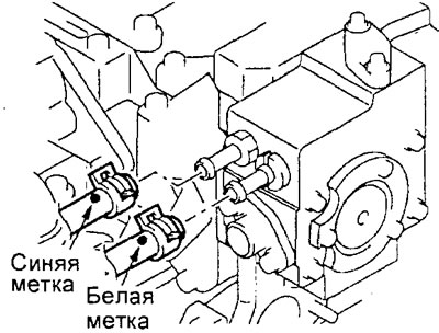
Engine 4G15.
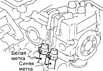
Engine 4G93.
5. Installing the lower and upper radiator hoses.
A) When connecting the radiator hose, put the hose on the branch pipe until it stops against the protrusion of the branch pipe, then tighten the clamp.
b) The hose clamp should always be installed in the position in which the clamp was previously installed. Therefore, before installing the clamp, align the alignment marks on the hose clamp and radiator hose, then connect the hose.
After completing the installation of the parts, perform the following operations:
- A) Connect the exhaust pipe to the exhaust manifold.
- b) Install the hood.
- V) Adjust the tension of the accessory drive belts (see the relevant section of the chapter "Maintenance and general inspection and adjustment procedures").
- G) Install the battery tray and battery.
- d) Install the air filter.
- e) Fill with coolant.
- and) Install the engine crankcase guard.
- h) Perform High Pressure Fuel Line Bleeding Procedure (refer to the appropriate procedure for installing the injection pump in chapter "fuel injection system (GDI)").
- And) Check for fuel leaks.
- To) Install the decorative engine cover.