



Contents: Removal ⤓ Installation ⤓
Removal
Before you begin removing parts, perform the following operations.
a) Remove the decorative engine cover.
b) Release the residual pressure from the high-pressure line (see chapter "Fuel injection system (GDI)").
c) Remove the engine crankcase protective cover.
d) Drain the coolant and engine oil.
d) Remove the air filter.
e) Remove the battery and battery tray.
g) Remove the accessory drive belts and the timing belt.
c) Remove the cylinder head covers and cover gaskets.
i) (Engine 4G15) Remove the cooling system inlet pipe.
k) (Engine 4G93) Remove the thermostat housing assembly.
l) (Engine 4G15) Remove the generator adjusting bar.
m) (Engine 4G93) Remove the EGR valve servo.
The parts are removed in the order of numbers shown in the figure "Replacing the cylinder head gasket".
When removing parts, pay attention to the following operations:
1. (Engine 4G93) Removing the upper radiator hose.
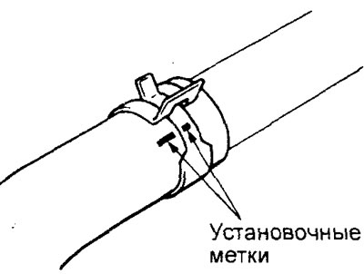
Before disconnecting the upper radiator hose, place relative position marks on the hose and hose clamp.
2. (Engine 4G93) Removing the camshaft pulley.
Secure the camshaft pulley from turning using a special fork holder and special bolts.
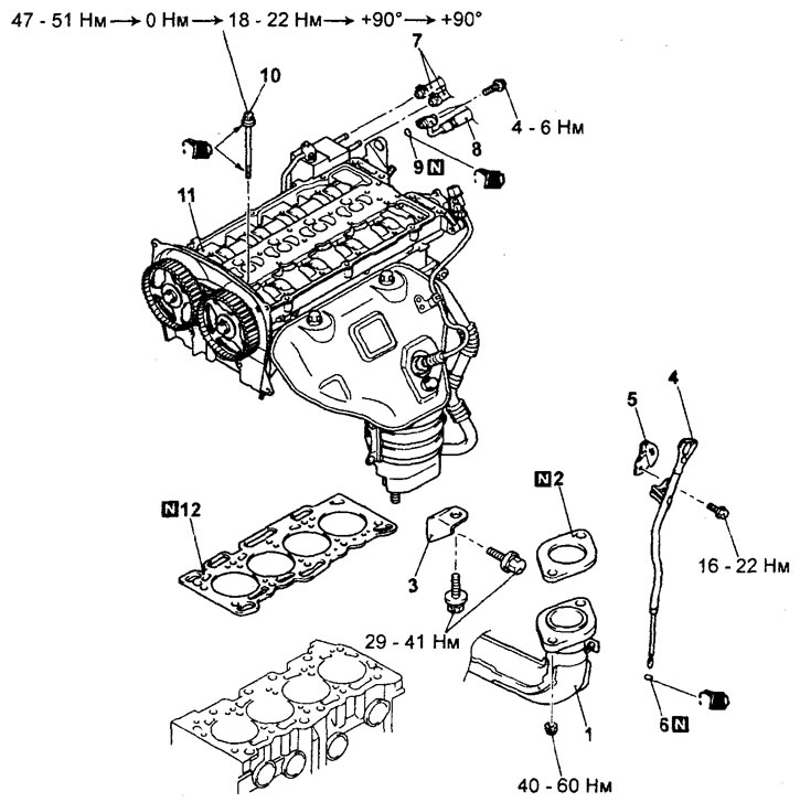
Replacing the cylinder head gasket (engine 4G15).1 - connection of the inlet pipe of the exhaust system, 2 - gasket, 3 - bracket of the exhaust manifold, 4 - guide tube and dipstick of the engine oil level in assembly, 5 - bracket of the engine suspension, 6 - ring gasket, 7 - connection of the fuel return hose, 8 - connection of the fuel inlet hose, 9 - ring gasket, 10 - bolt of fastening of the cylinder head, 11 - cylinder head in assembly, 12 - gasket of the cylinder head.
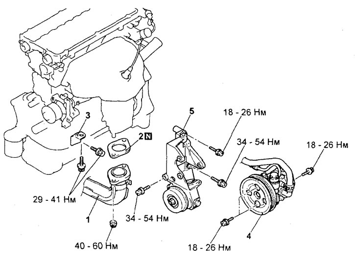
Replacing the cylinder head gasket (engine 4G93). 1 - connection of the exhaust system inlet pipe, 2 - gasket, 3 - bracket of the exhaust manifold, 4 - power steering pump, 5 - bracket of the power steering pump.
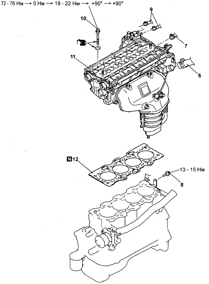
Replacing the cylinder head gasket (engine 4G93, continued). 6 - connection of the upper radiator hose, 7 - connection of the heater hose, 8 - bolt of the fastening of the clamp of the inlet pipe of the cooling system, 9 - connection of the fuel return hose, 10 - bolt of the fastening of the cylinder head, 11 - cylinder head assembly, 12 - cylinder head gasket.
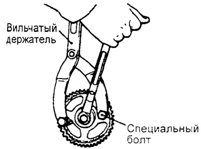
b) Loosen the camshaft pulley mounting bolt.
3. (Engine 4G93) Removing the power steering pump assembly with the bracket.
Remove the power steering pump assembly with the bracket and the hoses connected to it.
Note: Tie the removed power steering pump assembly with bracket and hoses with wire and place it in a place where it will not interfere with the removal and installation of the cylinder head assembly.
4. Removing the cylinder head.
a) Install the camshafts so that their guide pins are in the position shown in the figure.
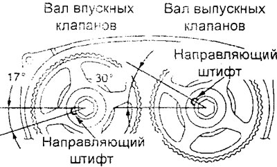
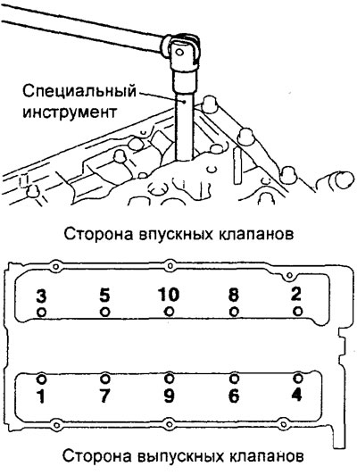
b) Using a special tool, loosen the mounting bolts in two or three steps (in the sequence shown in the figure), and then unscrew them, after which remove the cylinder head assembly.
Installation
Installation of parts is carried out in the reverse order of removal.
When installing the parts, please pay attention to the following operations.
1. Installing the cylinder head gasket.
a) Using a special scraper, remove the remains of the old cylinder head gasket from the cylinder block.
Caution: Be careful not to allow gasket material or other foreign particles to enter the cylinders, cooling system passages and lubrication system passages.
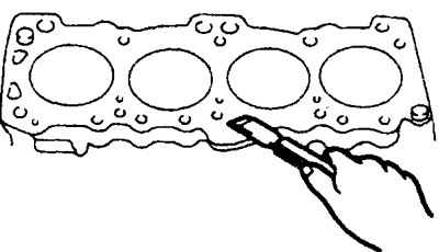
b) Degrease the working surface under the gasket on the cylinder block.
c) Ensure that the new cylinder head gasket has the correct identification mark for the engine in question.
d) Place the cylinder head gasket on the cylinder block.
Caution: Since there is a possibility of incorrect installation of the cylinder head gasket, check the correct installation of the gasket before installing the cylinder head (matching of all holes on the gasket and the cylinder head). If the gasket is incorrectly installed, malfunctions may occur, such as lack of oil access to the cylinder head.
2. Installing the cylinder head assembly.
a) Using a scraper, remove any remaining old cylinder head gasket from the cylinder head. Caution: Be careful not to allow gasket material or other foreign particles to enter the cooling system passages and lubrication system passages.
b) When installing the cylinder head mounting bolts, the length of the bolts must be within the permissible value. If the length of the bolts exceeds the maximum permissible value, the bolts must be replaced.
Maximum permissible value:
Engine 4G15 - no more than 103.2 mm
Engine 4G93 - no more than 96.4 mm
c) Lubricate the threads and washers of the cylinder head bolts with a small amount of clean engine oil.
d) Install the cylinder head bolt washers with the chamfered side facing up as shown in the illustration.
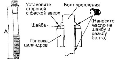
d) Before installation, lubricate the top surface of the washer and the bolt threads with a small amount of engine oil.
e) Tighten the cylinder head mounting bolts using the angular tightening method in the following order (tightening is performed in the sequence of numbers shown in the figure):
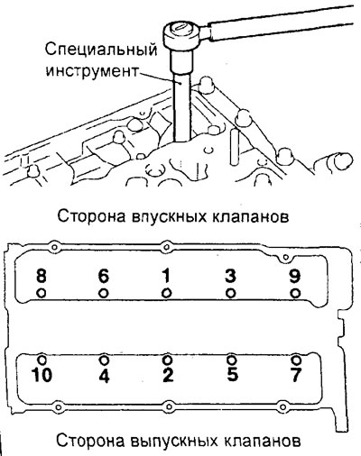
Engine 4G15:
- (1) Tighten all bolts to a torque of 49±2 N·m in the order shown in the figure;
- (2) Completely loosen all bolts in the reverse order of the illustration.
- (3) Tighten all bolts to a torque of 20±2 N·m in the order shown in the figure;
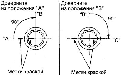
- (4) Tighten all bolts 90° (1/4 turn, from position "A" to position "B") in the order shown in the figure;
- (5) Tighten all bolts a final 90° (1/4 turn, from position "B" to position "C") in the order shown in the illustration.
Engine 4G93:
- (1) Tighten all bolts to a torque of 74±2 N·m in the order shown in the figure;
- (2) Completely loosen all bolts in the reverse order of the illustration.
- (3) Tighten all bolts to 20 + 2 N·m in the order shown in the figure;
- (4) Tighten all bolts 90° (1/4 turn, from position "A" to position "B") in the order shown in the figure;
- (5) Tighten all bolts a final 90° (1/4 turn, from position "B" to position "C") in the order shown in the illustration.
Note:
- After tightening, the marks on the bolts and cylinder head should be in line ("C").
- If the cylinder head mounting bolt is turned at an angle less than 90° (1/4 turn), the bolt will not be tightened sufficiently (the reliability of the gas joint will not be ensured).
- If the cylinder head mounting bolt is tightened to a torque exceeding the nominal value, then completely unscrew the mounting bolts and perform the bolt tightening procedure, starting with subparagraph "b".
3. (Engine 4G93) Installing the camshaft pulley.
a) Secure the camshaft pulley from turning using a special fork holder and special bolts.
b) Tighten the camshaft pulley mounting bolt to the specified torque.
Tightening torque: 89 ±9 Nm
4. (Engine 4G15) Installing the O-ring and fuel inlet hose.
a) Apply a small amount of clean engine oil to the O-ring of the fuel inlet hose.
Caution: Do not allow engine oil to enter the injection pump.
b) Be careful not to damage the O-ring during installation.
Connect the fuel hose flange to the injection pump by rotating it from side to side. After connecting, check that the flange rotates freely, without jamming.
c) If the fuel hose flange does not rotate smoothly, the O-ring may be pinched. In this case, disconnect the fuel hose, check the condition of the O-ring, and replace it if necessary. Reconnect the fuel hose and check the flange for smooth rotation again.
d) Tighten the hose mounting bolts to the specified torque.
Tightening torque: 5 ±1 Nm
5. Installing the fuel return hose.
Install the fuel return hose so that the identification mark is directed as shown in the illustration.
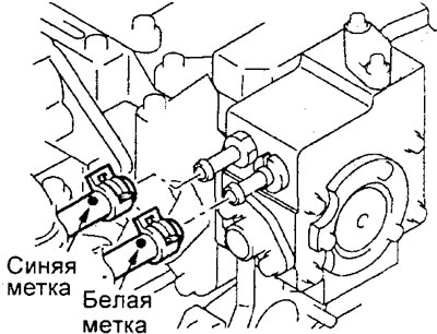
Engine 4G15.
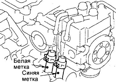
Engine 4G93.
6. (Engine 4G93) Installing the upper radiator hose.
a) When connecting the upper radiator hose, push the hose onto the pipe until it rests against the protrusion on the pipe, then tighten the clamp.
b) The hose clamp should always be installed in the position in which the clamp was previously installed. Therefore, before installing the clamp, align the installation marks on the hose clamp and the radiator hose, then connect the hose.
After completing the installation of the parts, perform the following operations:
- a) (Engine 4G93) Install the EGR valve servo.
- b) (Engine 4G15) Install the generator adjusting bar.
- c) (Engine 4G93) Install the thermostat housing assembly.
- d) (Engine 4G15) Install the cooling system inlet pipe.
- d) Install the cover gaskets and cylinder head cover.
- e) Install the timing belt and accessory drive belts.
- g) Adjust the tension of the drive belts of the attachments (see the relevant section of the chapter "Maintenance and general check and adjustment procedures").
- c) Install the battery tray and battery.
- i) Install the air filter.
- k) Fill with coolant and engine oil.
- l) Install the engine crankcase protective cover.
- m) Perform the procedure for bleeding air from the high-pressure fuel line (see the corresponding procedure when installing the injection pump in the chapter "Fuel injection system (GDI)").
- n) Check for fuel leaks.
- o) Install the decorative engine cover.