



Removal
1. Disconnect the cable from the negative terminal of the battery.
2. Remove the fuel pressure in the fuel system.
3. Drain the coolant from the engine cooling system.
4. Remove the air intake hose.
5. Remove the timing belt.
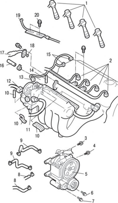
Fig. 3.38. Connecting connectors and hoses to the SOHC engine cylinder head: 1 – high-voltage wire tips; 2 – injector connectors; 3 – bolt, 22 Nm; 4 – bolt, 44 Nm; 5 – bracket and power steering pump assembly; 6 – bolt, 49 Nm; 7 – bolt, 44 Nm; 8 – connection of heater hoses; 9 – connection of cooling system hoses; 10 – Vacuum hose connection; 11 – throttle position sensor connector; 12 – idle speed control servo connector; 13 – Accelerator pedal position sensor connector (vehicles with TCL system); 14 – brake booster hose connection; 15 – ignition distributor connectors; 16 – Fuel return hose connection; 17 – High pressure fuel hose connection; 18 – O-ring gasket; 19 – accelerator pedal cable; 20 – bolt, 10 Nm
6. Loosen the bolts and disconnect the accelerator pedal cable 19 (Fig. 3.38).
7. Pull up and remove the high-voltage wire tips 1.
8. Disconnect the connectors of the throttle position sensor 11, idle speed control servo 12, accelerator pedal position sensor (vehicles with TCL system) 13, ignition distributor 15 and injectors 2.
9. Loosen the clamp and disconnect the fuel return hose 16.
10. Unscrew the bolts, disconnect the high pressure fuel hose and remove gasket 18.
11. Disconnect the brake booster hose 14.
12. Disconnect vacuum hose 10.
13. Loosen the clamps and disconnect the cooling system hoses 9.
14. Loosen the clamps and disconnect the heater hoses 8.
15. Loosen the bolts and remove the bracket and unit 5 of the power steering pump together with the hoses connected to it.
16. Tie the removed power steering pump assembly with the bracket and hoses with wire and place it so that it does not interfere with the removal and installation of the cylinder head assembly.

Fig. 3.39. Cylinder head gasket for SOHC engines: 1 – forced crankcase ventilation hose; 2 – cylinder head cover; 3 – radiator hose connection; 4 – PCV exhaust hose; 5 – rear timing belt cover; 6 – bolt, 10–12 Nm; 7 – camshaft pulley; 8 – bolt, 88 Nm; 9 – cylinder head gasket; 10 – gasket; 11 – bolt, 49 Nm; 12-intake pipe of the exhaust gas system; 13 – bolt, 50 Nm; 14 – bolt, 26–33 Nm; 15 – radiator hose connection; 16 – O-ring gasket; 17 – inlet pipe and thermostat in the housing assembly; 18 – bolt, 22–25 Nm; 19 – cylinder head assembly; 20 – spark plug guide tube sealing ring; 21 – cylinder head mounting bolt, 78 Nm +0 Nm + 20 Nm + 90° + 90°
17. Loosen the clamp and disconnect radiator hose 3 (Fig. 3.39).
18. Loosen the bolts and remove the inlet pipe and thermostat in the housing assembly 17 and the ring gasket 16.
19. Disconnect positive crankcase ventilation hose 1 and PCV hose 4.
20. Loosen the bolts and remove the cylinder head cover 2.
21. Using a special device, secure the camshaft pulley from turning, unscrew the bolt and remove the camshaft pulley.
22. Loosen the bolts and remove the rear cover 5 of the timing belt.
23. Unscrew the nuts and remove the exhaust pipe 12 and gasket 10 of the exhaust system.
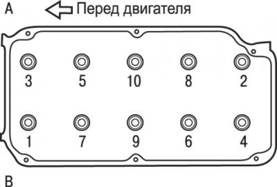
Fig. 3.40. Sequence for unscrewing the cylinder head mounting bolts: A - intake valve side; B – exhaust valve side
24. Unscrew the cylinder head mounting bolts 21 in 2 or 3 stages in the sequence shown in Fig. 3.40, and then remove the cylinder head assembly.
Caution! When unscrewing the cylinder head mounting bolts, be careful not to damage or deform the spark plug guide tubes, as they are not replaceable.
25. Remove the sealing rings 20 (see Fig. 3.39) of the spark plug guide tubes.
26. Carefully remove the cylinder head 19 assembly.
27. Remove cylinder head gasket 9.
Preparing for installation
1. The mating surfaces of the cylinder head and block must be completely clean. Use a hard plastic or wooden scraper to clean them. Be careful when cleaning, as the aluminum alloy is very easy to damage. Check that carbon deposits do not get into the channels of the lubrication and cooling systems. This is especially important for the lubrication system, as carbon deposits can block the supply of oil to engine components. Clean the channels if necessary.
2. Check the mating surfaces of the cylinder head and block for nicks, deep scratches and other damage. Minor damage can be removed by mechanical treatment. However, if there is significant damage, the parts must be replaced.
3. Using a metal ruler and feeler gauge, check the flatness of the mating surfaces.
4. Clean the bolt holes in the cylinder block. Screwing a bolt into an oil-filled hole can cause the block to burst due to hydraulic pressure.
Installation
Installation is carried out in the reverse order of removal, taking into account the following.
1. Degrease the mating surfaces of the gasket.
2. Check that all holes on the gasket and cylinder head are aligned.
3. Before installing the bolts, check the length of the bolt shaft (to the head), which should be no more than 96.4 mm. If this value is exceeded, the bolt must be replaced.
4. The bolt washer should be installed so that the chamfered surface of the washer is on top.
5. Before installation, lubricate the top surface of the washer and the bolt threads with a small amount of engine oil.
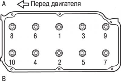
Fig. 3.41. Sequence of screwing in the cylinder head mounting bolts: A - intake valve side; B – exhaust valve side
6. Tighten the cylinder head bolts in several stages in the sequence shown in Fig. 3.41.
Bolt tightening steps:
- 1st - tighten to 78 Nm;
- 2nd – completely loosen all bolts in the reverse order shown in Fig. 3.41;
- 3rd – tighten to 20 Nm;
- 4th – tighten the bolts by 90°. Apply paint marks on the bolt heads and cylinder head;
- 5th – tighten the bolts another 90°. The marks on the bolts and the cylinder head should be in line.
Attention! Always screw the bolt in at an angle exactly equal to 90°. Otherwise, the cylinder head mounting bolt may become loose (the connection will not be secure). If the bolt is turned at an angle greater than 90°, it must be completely loosened and all bolt tightening operations must be repeated.
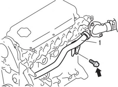
Fig. 3.42. Location of the fastening bolt for the supply pipe (1) of the cooling system
7. When installing the cooling system supply pipe, loosen the supply pipe mounting bolt as shown in Fig. 3.42.
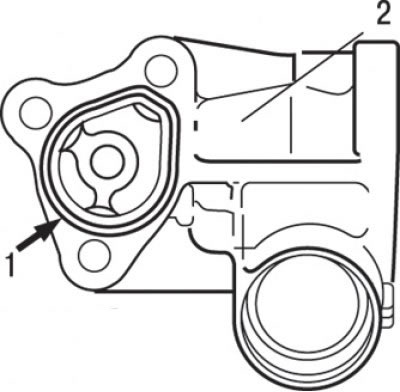
Fig. 3.43. Place of application (1) of sealant in the form of a bead with a diameter of 3±0.5 mm Mitsubishi Genuine Part MD970389 or similar to it on the mating surface of the inlet pipe (2)
8. When installing the inlet pipe and thermostat assembly, apply a layer of sealant to the mating surface of the inlet pipe (Fig. 3.43).
9. Moisten the O-ring seal of the cooling system supply pipe with water and insert the thermostat housing into the cooling system supply pipe.
10. Tighten the thermostat housing assembly mounting bolts.
11. Tighten the cooling system supply pipe mounting bolt.
12. When installing the camshaft pulley, secure the pulley from turning with a special tool, as when removing it, and tighten the bolt to a torque of 88 N·m.
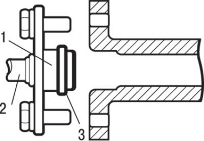
Fig. 3.44. Installing the high pressure fuel hose: 1 – place of lubrication with engine oil; 2 – high pressure fuel hose; 3 – O-ring gasket
13. When installing the high-pressure fuel hose, lubricate the O-ring with a small amount of clean engine oil (Fig. 3.44).
Caution! Do not allow oil to enter the fuel rail.
14. While slightly turning the flange of the fuel hose to the right and left, carefully insert it into the fuel rail to avoid damaging the O-ring seal. After installation, check that the hose rotates smoothly in the fuel rail.
15. If the hose flange sticks when turning, the cause may be damage to the O-ring. Disconnect the flange (assembled with the hose) from the fuel rail and inspect the gasket for damage, then insert it back and check for smooth turning.
16. Tighten the mounting bolts.
17. Install the timing belt.
18. Install the air intake hose.
19. Fill the cooling system with coolant.
20. Adjust the accelerator pedal cable.