



Share with friends:
Brake system of the car Mitsubishi Carisma


General information about steering
This braking system provides a high degree of reliability and durability combined with increased braking efficiency and sensitivity. The anti-lock braking system (ABS)...
This braking system provides a high degree of reliability and durability combined with increased braking efficiency and sensitivity. The anti-lock braking system (ABS)...
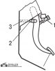
Checking and adjusting the brake pedal
Fig. 14.1. Measuring the height of the brake pedal position (nominal value 163.5–166.5 mm): 1 – brake light switch; 2 – pusher lock nut; 3 – pusher Measure the pedal...
Fig. 14.1. Measuring the height of the brake pedal position (nominal value 163.5–166.5 mm): 1 – brake light switch; 2 – pusher lock nut; 3 – pusher Measure the pedal...

Checking the brake light switch
Fig. 14.4. Checking the brake light switch Connect a universal tester to the brake light switch and check the brake light switch circuit with the pusher pressed and...
Fig. 14.4. Checking the brake light switch Connect a universal tester to the brake light switch and check the brake light switch circuit with the pusher pressed and...
Checking the performance of the brake booster
A simple check of the brake booster operation is carried out as follows. 1. Run the engine for 1-2 minutes and turn it off. If the first time you press the brake pedal,...
A simple check of the brake booster operation is carried out as follows. 1. Run the engine for 1-2 minutes and turn it off. If the first time you press the brake pedal,...
Checking the functionality of the brake booster check valve
1. Remove the vacuum hose. Caution! Do not disconnect the check valve from the vacuum hose. 2. Check the operation of the check valve using a vacuum pump. The valve is...
1. Remove the vacuum hose. Caution! Do not disconnect the check valve from the vacuum hose. 2. Check the operation of the check valve using a vacuum pump. The valve is...

Checking the functionality of the rear brake pressure regulator
Fig. 14.5. Connecting pressure gauges to the input and output of the pressure regulator respectively: 1 – pressure gauge; 2 – pressure regulator 1. Connect two pressure...
Fig. 14.5. Connecting pressure gauges to the input and output of the pressure regulator respectively: 1 – pressure gauge; 2 – pressure regulator 1. Connect two pressure...
Checking the brake fluid level sensor
By pressing the float of the brake fluid level sensor, check the condition of the circuit between the sensor terminals. The sensor is in good condition if the following...
By pressing the float of the brake fluid level sensor, check the condition of the circuit between the sensor terminals. The sensor is in good condition if the following...

Bleeding air from the hydraulic brake drive
Caution: Use only DOT 3 or DOT 4 brake fluid. Avoid mixing the recommended fluid with other types of brake fluid. Bleeding the Master Cylinder There is no check valve on...
Caution: Use only DOT 3 or DOT 4 brake fluid. Avoid mixing the recommended fluid with other types of brake fluid. Bleeding the Master Cylinder There is no check valve on...

Checking and replacing front disc brake pads
The brake pads have wear indicators which, when touching the brake disc, when the brake lining thickness reaches less than 2 mm, produce a squealing sound during...
The brake pads have wear indicators which, when touching the brake disc, when the brake lining thickness reaches less than 2 mm, produce a squealing sound during...
Checking the thickness of the brake disc
1. Using a micrometer, measure the thickness of the brake disc at eight points approximately every 45° at a distance of 10 mm from the outer edge of the disc. The...
1. Using a micrometer, measure the thickness of the brake disc at eight points approximately every 45° at a distance of 10 mm from the outer edge of the disc. The...

Checking the brake disc runout
Fig. 14.10. Location of bolts (arrows) for fastening the front brake caliper 1. Loosen the two bolts and remove the disc brake caliper assembly, lift it up and secure it...
Fig. 14.10. Location of bolts (arrows) for fastening the front brake caliper 1. Loosen the two bolts and remove the disc brake caliper assembly, lift it up and secure it...

Correction of brake disc runout
1. If the brake disc runout is within or exceeds the limit value, it is necessary to change the relative position of the disc and hub and then measure the runout again....
1. If the brake disc runout is within or exceeds the limit value, it is necessary to change the relative position of the disc and hub and then measure the runout again....
Checking the thickness of the brake shoe linings of drum brakes
1. Remove the brake drum. 2. Measure the thickness of the pad at the point of greatest wear: nominal thickness – 4.4 mm; minimum thickness – 1.0 mm. 3. If the lining...
1. Remove the brake drum. 2. Measure the thickness of the pad at the point of greatest wear: nominal thickness – 4.4 mm; minimum thickness – 1.0 mm. 3. If the lining...

Brake pedal — removal and installation
Removal To remove the brake pedal, perform the following steps. 1. Remove the lower instrument panel trim. 2. Remove the steering column assembly. 3. Remove the relay...
Removal To remove the brake pedal, perform the following steps. 1. Remove the lower instrument panel trim. 2. Remove the steering column assembly. 3. Remove the relay...

Master cylinder and brake booster
Removal To remove the clutch pedal, perform the following operations in sequence. 1. Drain the brake fluid. Fig. 14.13. Master brake cylinder and brake booster: 1 –...
Removal To remove the clutch pedal, perform the following operations in sequence. 1. Drain the brake fluid. Fig. 14.13. Master brake cylinder and brake booster: 1 –...

Repair of the main brake cylinder
Disassembly To disassemble the brake master cylinder, perform the following operations in sequence. Fig. 14.16. Master brake cylinder: 1 – tank lock bolt; 2 – brake...
Disassembly To disassemble the brake master cylinder, perform the following operations in sequence. Fig. 14.16. Master brake cylinder: 1 – tank lock bolt; 2 – brake...

Front Disc Brakes — Removal and Installation
Removal To remove the front disc brake, perform the following operations in sequence. 1. Drain the brake fluid. Fig. 14.20. Front disc brakes: 1 – hollow bolt (15 Nm); 2...
Removal To remove the front disc brake, perform the following operations in sequence. 1. Drain the brake fluid. Fig. 14.20. Front disc brakes: 1 – hollow bolt (15 Nm); 2...

Front Disc Brake Caliper
Disassembly To disassemble the front disc brake caliper, perform the following operations in sequence. Fig. 14.24. Front disc brake caliper: 1 – bolt (27 Nm); 2 – bolt...
Disassembly To disassemble the front disc brake caliper, perform the following operations in sequence. Fig. 14.24. Front disc brake caliper: 1 – bolt (27 Nm); 2 – bolt...

Rear Drum Brakes — Removal and Installation
Rear drum brakes for cars produced since 1996 Removal To remove the rear drum brakes, perform the following operations in sequence. 1. Loosen the parking brake adjusting...
Rear drum brakes for cars produced since 1996 Removal To remove the rear drum brakes, perform the following operations in sequence. 1. Loosen the parking brake adjusting...

Wheel brake cylinder — removal, inspection and installation
Removal To remove the wheel cylinder, perform the following operations sequentially. Fig. 14.34. Working brake cylinder: 1 – anther; 2 – piston assembly; 3 – piston; 4 –...
Removal To remove the wheel cylinder, perform the following operations sequentially. Fig. 14.34. Working brake cylinder: 1 – anther; 2 – piston assembly; 3 – piston; 4 –...

Rear Disc Brakes — Removal, Checking and Installation
Removal To remove the rear disc brakes, perform the following operations in sequence. 1. Loosen the parking brake adjusting nut. 2. Drain the brake fluid. Fig. 14.36....
Removal To remove the rear disc brakes, perform the following operations in sequence. 1. Loosen the parking brake adjusting nut. 2. Drain the brake fluid. Fig. 14.36....

Repair of rear disc brake caliper
Disassembly To disassemble the rear disc brake caliper, perform the following operations in sequence. Fig. 14.38. Rear disc brake caliper: 1 – return spring; 2 – parking...
Disassembly To disassemble the rear disc brake caliper, perform the following operations in sequence. Fig. 14.38. Rear disc brake caliper: 1 – return spring; 2 – parking...

Brake pads of the rear disk brake
Removal To remove the rear disc brake pads, perform the following operations in sequence. Fig. 14.38. Rear disc brake caliper: 1 – return spring; 2 – parking brake...
Removal To remove the rear disc brake pads, perform the following operations in sequence. Fig. 14.38. Rear disc brake caliper: 1 – return spring; 2 – parking brake...

Connecting the brake pipes to the pressure regulator
Fig. 14.43. Connecting the brake pipes to the pressure regulator: 1 – pressure regulator (left rear wheel brake mechanism); 2 – pressure regulator (brake mechanism of...
Fig. 14.43. Connecting the brake pipes to the pressure regulator: 1 – pressure regulator (left rear wheel brake mechanism); 2 – pressure regulator (brake mechanism of...

Anti-lock braking system
During heavy braking, the wheel may slip on the surface. The circumferential speed of the wheel in this case is less than the speed of the car. Slip is minimal (0%) when...
During heavy braking, the wheel may slip on the surface. The circumferential speed of the wheel in this case is less than the speed of the car. Slip is minimal (0%) when...

Checking and clearing ABS fault codes
Fig. 14.44. Connection to the ground of contact No.1 of the diagnostic connector using a special wiring harness 1. Using a special wire harness, connect contact No.1 of...
Fig. 14.44. Connection to the ground of contact No.1 of the diagnostic connector using a special wiring harness 1. Using a special wire harness, connect contact No.1 of...
Resistance between ABS connector contacts on the wiring harness side
1. Before checking the circuit condition and resistance, turn the ignition switch to the "OFF" position and disconnect the connector from the ABS control unit. Fig....
1. Before checking the circuit condition and resistance, turn the ignition switch to the "OFF" position and disconnect the connector from the ABS control unit. Fig....

Starting the engine with a completely discharged battery
If, with a completely discharged battery, an external power source is connected via connecting wires to start the engine and the car immediately starts moving (without...
If, with a completely discharged battery, an external power source is connected via connecting wires to start the engine and the car immediately starts moving (without...

Hydraulic block — removal and installation
Removal To remove the hydraulic unit, perform the following operations. 1. Drain the brake fluid. 2. Remove the air conditioner relay box. Fig. 14.47. Direction of...
Removal To remove the hydraulic unit, perform the following operations. 1. Drain the brake fluid. 2. Remove the air conditioner relay box. Fig. 14.47. Direction of...

Wheel speed sensor — removal, inspection and installation
Removal To remove the wheel speed sensor, perform the following steps. Front wheel Fig. 14.50. Front and rear wheel speed sensors: 1 – front wheel speed sensor rotor; 2...
Removal To remove the wheel speed sensor, perform the following steps. Front wheel Fig. 14.50. Front and rear wheel speed sensors: 1 – front wheel speed sensor rotor; 2...

Checking the Wheel Speed Sensor Insulation
Fig. 14.53. Checking the insulation of the wheel speed sensor 1. Disconnect all wires from the sensor and then measure the resistance between contacts 1, 2 and the...
Fig. 14.53. Checking the insulation of the wheel speed sensor 1. Disconnect all wires from the sensor and then measure the resistance between contacts 1, 2 and the...

Checking the travel of the parking brake lever
1. Pull the parking brake lever with a force of approximately 196 N and count the number of clicks, which should be 5-7. Attention! It is necessary to strictly observe...
1. Pull the parking brake lever with a force of approximately 196 N and count the number of clicks, which should be 5-7. Attention! It is necessary to strictly observe...

Checking the Parking Brake Indicator Light Switch
Fig. 14.56. Connecting a measuring device to check the parking brake indicator lamp switch Check the circuit between the switch terminal and the switch mounting bolt....
Fig. 14.56. Connecting a measuring device to check the parking brake indicator lamp switch Check the circuit between the switch terminal and the switch mounting bolt....

Parking brake lever — removal and installation
Removal To remove the parking brake lever, perform the following operations. 1. Remove the floor console. 2. Remove the rear seat. Fig. 14.57. Parking cable lever: a –...
Removal To remove the parking brake lever, perform the following operations. 1. Remove the floor console. 2. Remove the rear seat. Fig. 14.57. Parking cable lever: a –...

Parking brake cable — removal and installation
Removal To remove the parking brake cable, perform the following steps. Remove the floor console. Parking brake cable for vehicles with rear drum brakes Fig. 14.58....
Removal To remove the parking brake cable, perform the following steps. Remove the floor console. Parking brake cable for vehicles with rear drum brakes Fig. 14.58....
This section is available on: russian, bulgarian, belarusian, ukrainian, serbian, croatian, romanian, polish, slovak, hungarian
Similar materials for other Mitsubishi models
➤ Chassis and running gear: Brake system Mitsubishi Colt 4 and 5 (1991-2003)
➤ Chassis and running gear: Brake system Mitsubishi Lancer 9 (2000-2007, petrol)
➤ Chassis and running gear: Brake system Mitsubishi Galant 5 (1983-1989, petrol)
➤ Chassis and running gear: Brake system Mitsubishi L200 4 (2005-2014, diesel)
➤ Chassis and running gear: Brake system Mitsubishi Outlander 1 (2003-2008)
➤ Chassis and running gear: Brake system Mitsubishi Pajero 1 and 2 (1982-1999)
Link in different formats to this section
TEXTHTMLBB Code
- General information
- User manual
- Maintenance
- Power unit
- Petrol engines 4G9
- Diesel engines FBQT
- Diesel engines F9Q
- Cooling system
- Injection system (MPI)
- Injection system (GDI)
- Engine electrical equipment
- Transmission
- Clutch
- Mechanical gearbox
- Automatic gearbox
- Chassis and running gear
- Steering
- Brake system
- Front suspension and shafts
- Rear suspension
- Body and interior
- Exterior (external elements)
- Interior (internal elements)
- Doors, locks and windows
- Air conditioner
- Electrical equipment
- Equipment and devices
- Headlights and lighting
- Electrical circuits
- General information
- User manual
- Maintenance
- Power unit
- Petrol engines 4G9
- Petrol engines 4G1
- Diesel engines F9Q1
- Cooling system
- Fuel injection system GDI
- Fuel injection system MPI
- Diesel supply system F9Q1
- Ignition system
- Diesel preheating
- Transmission
- Clutch
- Mechanical gearbox
- Automatic gearbox
- Chassis and running gear
- Suspension and drive shafts
- Brake system
- Steering
- Body and interior
- Exterior (external elements)
- Interior (internal elements)
- Doors, locks and windows
- Heating and air conditioning
- Electrical equipment
- Power devices
- Equipment and devices