



Rear drum brakes for cars produced since 1996
Removal
To remove the rear drum brakes, perform the following operations in sequence.
1. Loosen the parking brake adjusting nut.
2. Drain the brake fluid.
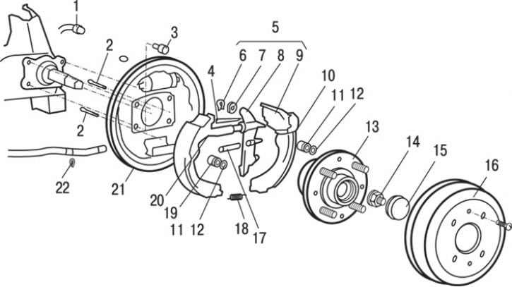
Fig. 14.27. Rear drum brakes: 1 – brake pipe connection (15 Nm); 2 – brake shoe holder; 3 – bolt (60 Nm); 4 – upper return spring; 5 – brake shoe and parking brake lever assembly; 6 – retainer; 7 – convex washer; 8 – parking brake lever; 9 – brake shoe with lining assembly; 10 – automatic regulator lever; 11 – brake shoe holder spring; 12 – Brake shoe holder cap; 13 – rear wheel hub assembly; 14 – hub flange nut (180 Nm); 15 – hub cap; 16 – brake drum; 17 – automatic regulator spring; 18 – lower return spring; 19 – brake shoe with lining assembly; 20 – automatic regulator assembly; 21 – drum brake support shield; 22 – retaining ring
3. Remove brake drum 16 (Fig. 14.27).
4. Remove spring 17 of the automatic regulator.
5. Remove the lever 10 of the automatic regulator.
6. Remove the automatic regulator 20 as an assembly.
7. Remove the lower return spring 18.
8. Remove cap 12 of the brake shoe holder.
9. Remove spring 11 of the brake shoe holder.
10. Remove the upper return spring 4.
11. Remove the brake shoe 19 with the lining assembly.
12. Remove the brake shoe and parking brake lever 5 as an assembly.
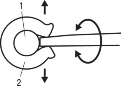
Fig. 14.28. Using a screwdriver to remove the retainer: 1 – finger; 2 – retainer
13. Remove the retainer 6. Using a flat-head screwdriver, release the retainer and remove it (Fig. 14.28).
14. Remove convex washer 7 (see Fig. 14.27).
15. Remove the parking brake lever 8.
16. Remove the brake shoe 9 with the lining assembly.
17. Remove the brake shoe holder 2.
18. Loosen the nut and disconnect the brake pipe 1.
19. Remove retaining ring 22.
20. Remove the hub cap 15.
21. Unscrew the flange nut 14 of the hub.
22. Remove the rear wheel hub assembly 13.
23. Remove the support shield 21 of the drum brake.
Installation
Installation is carried out in the reverse order of removal, taking into account the following.
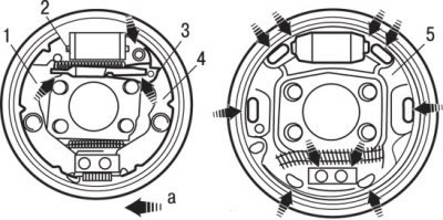
Fig. 14.29. Places (a) for applying plastic grease for brakes SAE J310, NLIGI No.1: 1 – brake shoe with lining assembly; 2 – automatic regulator assembly; 3 – automatic regulator lever; 4 – brake shoe with lining assembly; 5 – drum brake support shield
1. After installing the brake support shield, apply SAE J310, NLIGI No.1 plastic brake grease to certain points on the shield (Fig. 14.29).
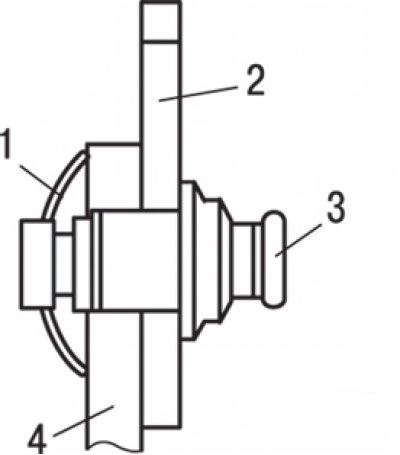
Fig. 14.30. Correct installation position of the convex washer: 1 – convex washer; 2 – brake shoe; 3 – finger; 4 – parking brake lever
2. Install the convex washer in the position shown in Fig. 14.30.
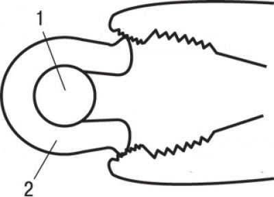
Fig. 14.31. Using pliers to install the retainer: 1 – brake shoe holder pin; 2 – retainer
3. Using pliers, install and tighten the retainer (Fig. 14.31).
4. Remove air from the hydraulic drive of the brake system.
5. Adjust the travel of the parking brake lever.
Rear drum brakes for cars produced since 1997
Removal
To remove the rear drum brakes, perform the following operations in sequence.
1. Loosen the parking brake adjusting nut.
2. Drain the brake fluid.
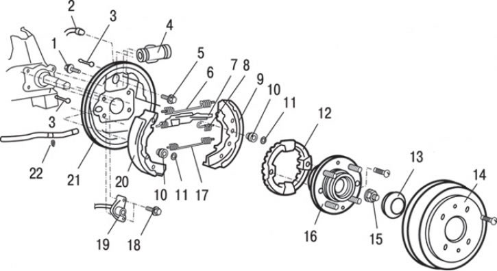
Fig. 14.32. Rear drum brakes of vehicles with ABS: 1 – bolt (8 Nm); 2 – brake pipe nipple (15 Nm); 3 – brake shoe holder pin; 4 – brake master cylinder assembly; 5 – bolt (60 Nm); 6 – upper tension spring; 7 – automatic gap adjuster; 8 – spring holding the parking brake drive lever; 9 – brake shoe with parking brake lever assembly; 10 – brake shoe holder spring; 11 – Brake shoe holder cap; 12 – toothed rotor (cars with ABS); 13 – hub cap; 14 – brake drum; 15 – flange nut (180 Nm); 16 – rear wheel hub assembly; 17 – lower brake shoe tension spring; 18 – bolt (60 Nm); 19 – wheel speed sensor (cars with ABS); 20 – brake shoe assembly; 21 – drum brake support shield; 22 – retaining ring
3. Remove brake drum 14 (Fig. 14.32).
4. Remove the upper tension spring 6.
5. Remove spring 8 holding the parking brake drive lever.
6. Remove the lower brake shoe tension spring 17.
7. Remove the automatic gap adjuster 7.
8. Remove cap 11 of the brake shoe holder.
9. Remove spring 10 of the brake shoe holder.
10. Remove the brake shoe 20 as an assembly.
11. Remove pin 3 of the brake shoe holder.
12. Remove the brake shoe 9 with the parking brake lever assembly.
13. Loosen the nut and disconnect the brake pipe 2.
14. Unscrew the two bolts and remove the working brake cylinder 4 as an assembly.
15. Remove the parking brake cable retaining ring 22.
16. Remove the hub cap 13.
17. Unscrew flange nut 15.
18. Remove the hub 16 of the rear wheel.
19. Remove toothed rotor 12 (vehicles with ABS).
20. Unscrew the two bolts securing the wheel speed sensor 19 (cars with ABS).
21. Remove the support shield 21 of the drum brake.
Installation
Installation is carried out in the reverse order of removal, taking into account the following.
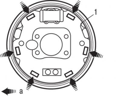
Fig. 14.33. Locations (a) for applying plastic grease for brakes SAE J310, NLIGI No.1 to the support shield (1) of the drum brake
1. After installing the brake support shield, apply SAE J310, NLIGI No.1 plastic brake grease to certain points on the shield (Fig. 14.33).
2. Remove air from the hydraulic drive of the brake system.
3. Adjust the travel of the parking brake lever.