



Contents: Removal ⤓ Installation ⤓
Removal
To remove the front disc brake, perform the following operations in sequence.
1. Drain the brake fluid.
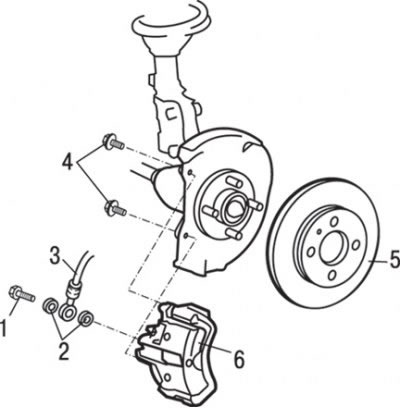
Fig. 14.20. Front disc brakes: 1 – hollow bolt (15 Nm); 2 – sealing ring; 3 – brake hose; 4 – bolt (100 Nm); 5 – brake disc; 6 – support
2. Unscrew the special bolt and disconnect the brake hose 3 (Fig. 14.20) from the caliper.
3. Remove the sealing rings 2.
4. Using a special tool, remove the brake disc 5 as an assembly.
Installation
Installation is carried out in the reverse order of removal, taking into account the following.
1. To measure the rotating resistance force after installing the brake pads, first measure the rotating resistance of the wheel hub bearing with the brake pads removed.
2. Remove the drive shaft.
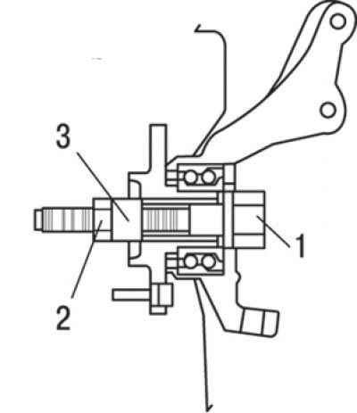
Fig. 14.21. Installation in the hub of a special device for measuring the resistance to rotation of the wheel hub bearing with the brake pads removed: 1 – bolt; 2 – nut (180 Nm); 3 – special device МВ990998
3. Install the special device into the hub as shown in Fig. 14.21 and tighten it to the required torque.
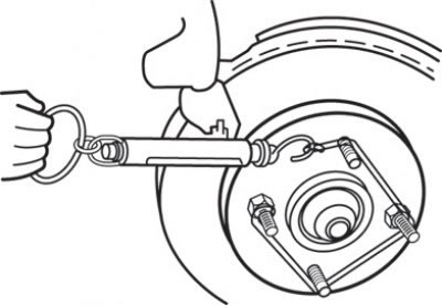
Fig. 14.22. Using a spring dynamometer to measure the rotating resistance of a hub bearing
4. To measure the rotational resistance of the hub bearing, use a spring dynamometer (Fig. 14.22).
5. After installing the caliper assembly onto the steering knuckle, install the brake pads assembly.
Caution! Do not allow oils, greases or other contaminants to come into contact with the working surfaces of the brake discs and brake shoe linings.
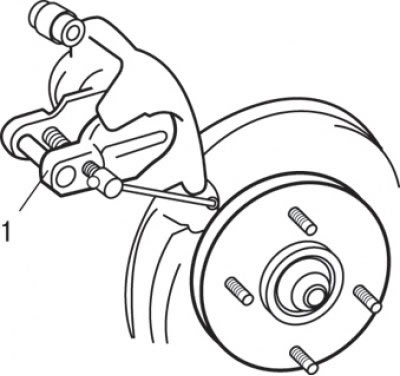
Fig. 14.23. Using the special tool MB990520 (1) to install the piston in the wheel brake cylinder
6. Clean the piston and insert it into the wheel brake cylinder (Fig. 14.23).
7. Be careful not to damage the piston boot when lowering the caliper assembly into place, then install the roll pin.
8. Measure the rotating resistance after installing new brake pads as follows:
- start the engine and press the brake pedal 2-3 times;
- stop the engine;
- make 10 forward turns of the brake disc.
9. Using a spring dynamometer, measure the moment of resistance to rotation of the wheel hub bearing during forward rotation (see Fig. 14.22).
10. Calculate the moment of resistance to rotation of new brake pads as the difference between the moments during rotation of the hub with brake pads and without brake pads, which should not exceed 40 Nm.
11. If the obtained torque difference exceeds the nominal value, replace the disc brake assembly.
12. Fill with brake fluid.
13. Remove air from the hydraulic drive of the brake system.