



Contents: Removal ⤓ Installation ⤓
Removal
To remove the rear disc brakes, perform the following operations in sequence.
1. Loosen the parking brake adjusting nut.
2. Drain the brake fluid.
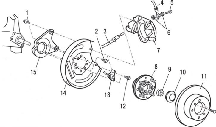
Fig. 14.36. Rear disc brakes: 1 – bolt (54 Nm); 2 – bolt (80 Nm); 3 – parking brake cable connection; 4 – brake hose connection; 5 – bolt (29 Nm); 6 – sealing ring; 7 – disc brake assembly; 8 – rear wheel hub and speed sensor rotor assembly; 9 – self-locking nut (172 Nm); 10 – hub cap; 11 – brake disc; 12 – bolt (65 Nm); 13 – rear wheel speed sensor; 14 – brake shield; 15 – Disc brake mounting plate
3. Disconnect cable 3 (Fig. 14.36) of the parking brake drive.
4. Loosen the nut and disconnect the brake hose 4.
5. Remove sealing ring 6.
6. Remove the disc brake assembly 7.
7. Remove the brake disc 11.
8. Remove the hub cover 10.
9. Unscrew the self-locking nut 9.
10. Remove the rear wheel hub and speed sensor rotor 8 as an assembly.
11. Unscrew the two bolts and, using a special tool, remove the rear wheel speed sensor 13.
12. Remove the brake shield 14.
13. Remove the disc brake mounting plate 15.
Installation
Installation is carried out in the reverse order of removal, taking into account the following.
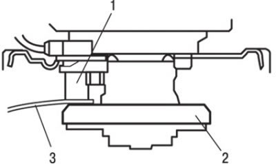
Fig. 14.37. Checking the gap between the rear wheel speed sensor tip and the toothed surface of the ABS sensor rotor: 1 – measuring probe; 2 – rear wheel speed sensor; 3 – ABS sensor rotor
When installing the rear wheel speed sensor, be careful when handling the tip (pole) of the sensor to avoid damaging it. Insert the measuring probe into the gap between the tip of the rear wheel speed sensor and the toothed surface of the ABS sensor rotor, check whether the gap corresponds to the nominal value along the entire perimeter (Fig. 14.37).
Nominal clearance: 0.1–1.9 mm.