



Disassembly
To disassemble the front disc brake caliper, perform the following operations in sequence.
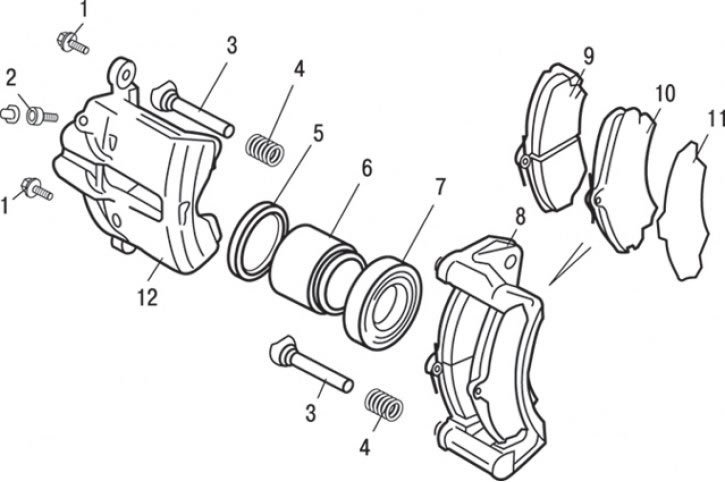
Fig. 14.24. Front disc brake caliper: 1 – bolt (27 Nm); 2 – bolt (7 Nm); 3 – guide pin; 4 – anther; 5 – piston sealing ring; 6 – piston; 7 – piston dust cover; 8 – caliper bracket; 9 – inner brake shoe; 10 – outer brake shoe; 11 – outer brake shoe plate; 12 – support
1. Unscrew the two bolts 1 (Fig. 14.24) securing the caliper.
2. Remove the caliper bracket 8.
3. Unscrew guide pin 3.
4. Remove the boot 4.
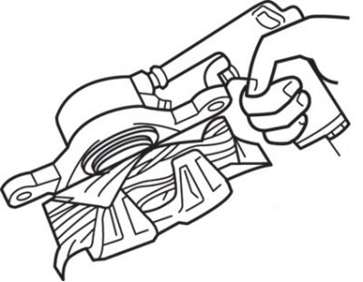
Fig. 14.25. Removing the piston from the caliper
5. Remove the piston (Fig. 14.25). To do this, place a wooden block between the piston and the outer part of the caliper body. To remove the dust cover and piston, apply compressed air to the hole in the brake hose.
Caution! If you suddenly inject air into the brake cylinder body, the piston will fly out and damage the caliper body. Inject compressed air gradually.
6. Remove piston dust cover 7 (see Fig. 14.24).
7. Use your finger to remove the sealing ring.
Caution: To prevent damage to the inner surface of the wheel cylinder, do not use a flat-head screwdriver or other tool.
8. Clean the piston and cylinder surfaces with trichloroethylene, alcohol, or recommended DOT 3 or DOT 4 brake fluid.
Examination
1. Check the brake cylinder for wear, damage or rust.
2. Check the piston surface for wear, damage or rust.
3. Check the caliper body and bushings for wear.
4. Check the brake shoe linings for damage or oil contamination, and the metal bases of the shoes for damage.
Assembly
Assembly is carried out in the reverse order of removal, taking into account the following.
The text of the article was taken from the website: MITSUBISHIMAN.ru
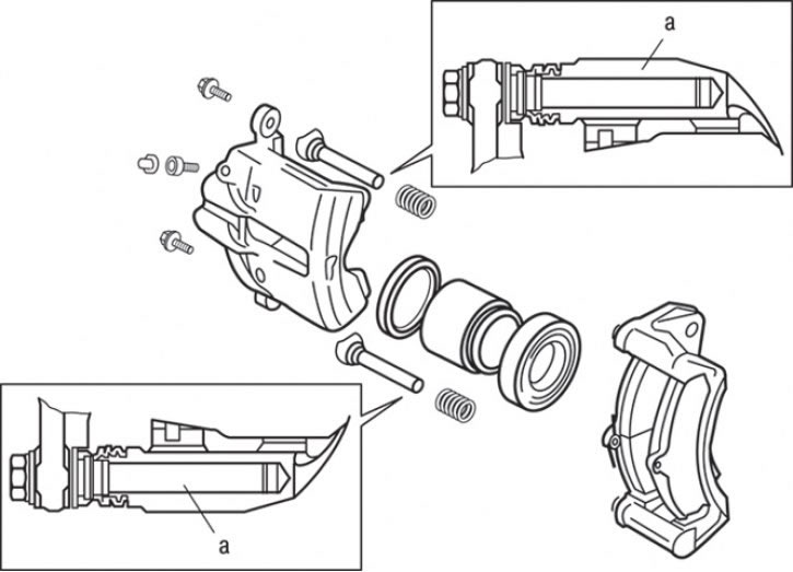
Fig. 14.26. Places (a) for applying grease from the repair kit to the guide pins during caliper assembly
Before installing the guide pins, apply grease from the repair kit to the working surface of the pin and to the hole in the caliper bracket into which the pin enters (Fig. 14.26).