



Disassembly
To disassemble the rear disc brake caliper, perform the following operations in sequence.
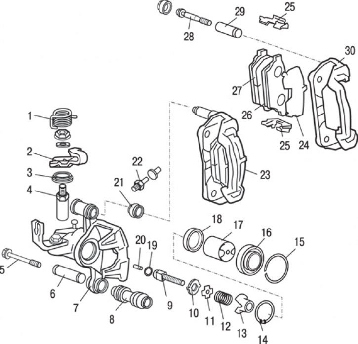
Fig. 14.38. Rear disc brake caliper: 1 – return spring; 2 – parking brake lever; 3 – lever dust cover; 4 – rod lever; 5 – lower guide pin (26 Nm); 6 – lower guide pin bushing; 7 – caliper body; 8 – lower guide pin boot; 9 – adjusting rod; 10 – limiter; 11 – limiter plate; 12 – return spring; 13 – spring housing; 14 – retaining ring; 15 – piston dust cover ring; 16 – piston dust cover; 17 – piston assembly; 18 – piston sealing ring; 19 – O-ring gasket; 20 – connecting rod; 21 – Upper guide pin boot; 22 – bleed nipple (7.8 Nm); 23 – caliper bracket (assembled with brake pads, pad guides and gasket); 24 – outer gasket; 25 – shoe guide; 26 – brake shoe assembly; 27 – brake shoe with wear indicator assembly; 28 – Upper guide pin (26 Nm); 29 – Upper guide pin bushing; 30 – caliper bracket
1. Unscrew the lower guide pin 5 (Fig. 14.38).
2. Lift up the bracket 23 of the caliper (assembled with the brake pads, pad guides and gasket).
3. Remove bushing 6 of the lower guide pin.
4. Remove the dust cover 8 of the lower guide pin.
5. Remove the dust cover 21 of the upper guide pin.
6. Remove ring 15 of the piston dust seal.
7. Remove the 16 piston dust cover.
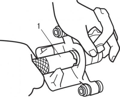
Fig. 14.39. Using special tool MB990652 (1) to unscrew the piston from the caliper body
8. Using a special tool, unscrew the piston from the caliper body (Fig. 14.39).
9. Use your finger to remove the sealing ring.
Caution: To prevent damage to the inner surface of the wheel cylinder, do not use a flat-head screwdriver or other tool.
10. Clean the piston and cylinder surfaces with trichloroethylene, alcohol, or recommended DOT 3 or DOT 4 brake fluid.
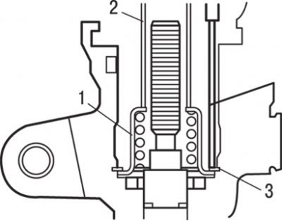
Fig. 14.40. Removing the retaining ring: 1 – spring housing; 2 – steel tube; 3 – spring retaining ring
11. Using a 19 mm diameter steel tube, press the spring housing against the caliper housing as shown in Fig. 14.40 and use the special tool to remove the retaining ring.
12. Remove spring housing 13 (see Fig. 14.38).
13. Remove return spring 12.
14. Remove the limiter plate 11.
15. Remove limiter 10.
16. Remove the adjusting rod 9.
17. Remove connecting rod 20.
18. Remove the O-ring 19.
19. Remove the lever 4 of the rod.
20. Remove the boot of the 3rd lever.
21. Remove parking brake lever 2.
22. Remove return spring 1.
23. Unscrew the bleed nipple 22.
24. Remove the caliper housing 7.
25. Remove the outer gasket 24.
26. Remove the brake shoe 26 as an assembly.
27. Remove the brake shoe 27 with the wear indicator assembly.
28. Remove the shoe guide 25.
29. Unscrew the upper guide pin 28.
30. Remove bushing 29 of the upper guide pin.
31. Remove the caliper bracket 30.
Examination
1. Check the brake cylinder for wear, damage or rust.
2. Check the piston surface for wear, damage or rust.
3. Check the caliper body and bushings for wear.
4. Check the brake shoe linings for damage or oil contamination, and the metal bases of the shoes for damage.
Assembly
Assembly is carried out in the reverse order of disassembly, taking into account the following
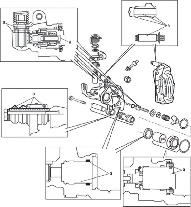
Fig. 14.41. Places (a) for applying grease from the repair kit to the caliper parts
1. When assembling the rear disc brake caliper, apply grease from the repair kit to the surfaces shown in Fig. 14.41.
Attention! The piston sealing ring and dust boot are coated with a special grease, so this grease must not be removed.
2. Using a steel tube with a diameter of about 19 mm and the special tool that were used during disassembly, install the retaining ring into place.
Caution! Install the retaining ring with the bleed nipple hole open.
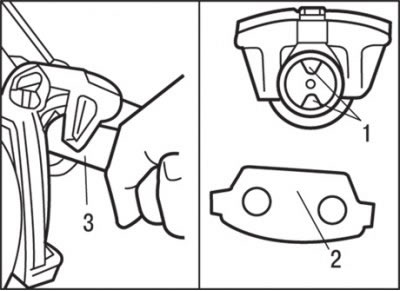
Fig. 14.42. Using a special tool to install the piston assembly: 1 – limiter grooves; 2 – ledge; 3 – special tool МВ990652
3. Using special tool MB990652 3 (Fig. 14.42), install the piston into the caliper body.
Attention! Arrange the grooves as shown in Fig. 14.41.
The projections on the rear of the brake pads must be located in the grooves of the piston.